PART 1: CX-Programmer
CHAPTER 2 – Quick Start Guide OMRON
CX-Programmer _Page 14
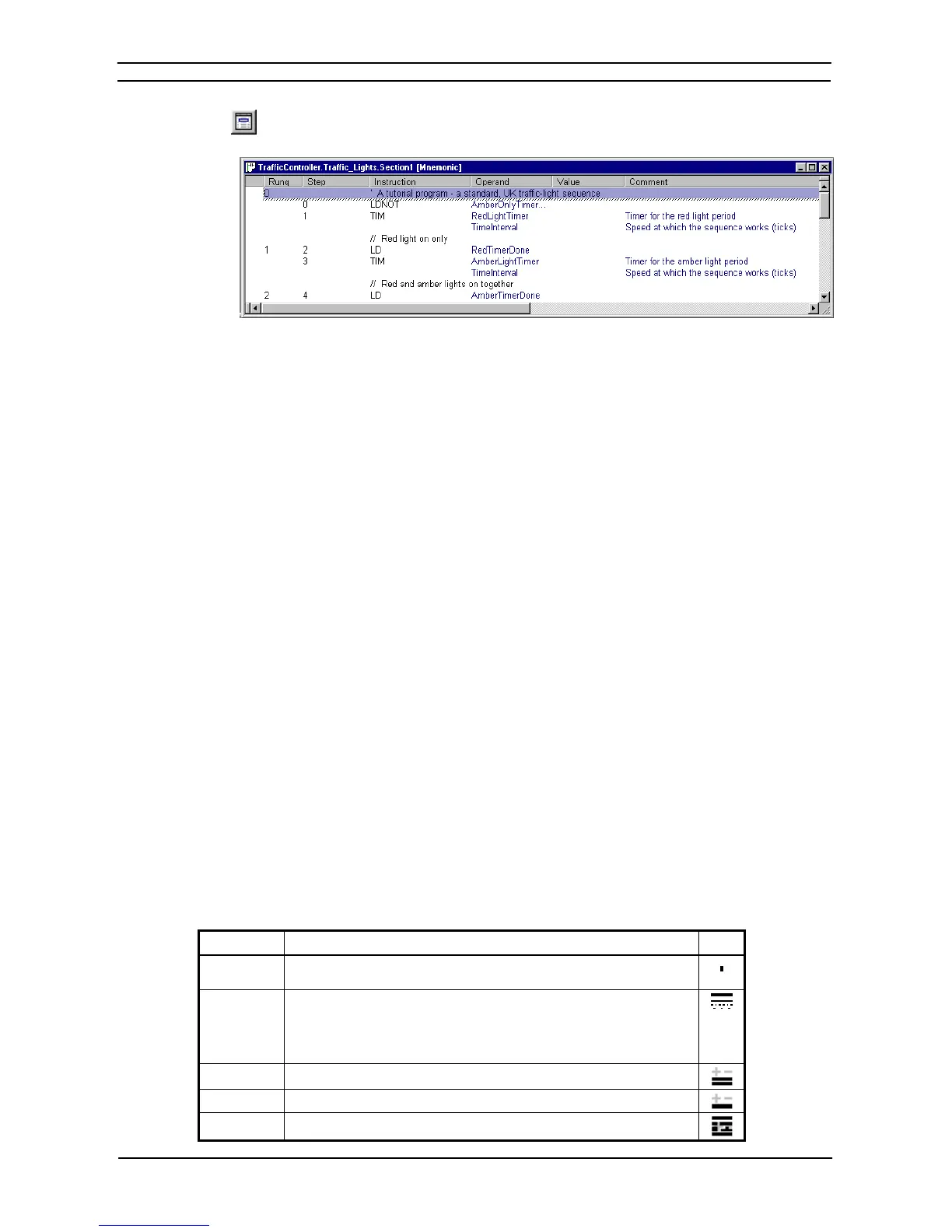
Select the View Mnemonics button from the toolbar. The Mnemonics view is displayed in the
Diagram Workspace.
1, 2, 3…
1. To program in mnemonics, open the mnemonic view and place the cursor on the desired
instruction.
2. Press ENTER – this will enter the editing mode.
3. Edit or type the new instruction lines. A mnemonic instruction consists of an instruction
name followed by a set of operands separated by spaces (e.g. ‘MOV #1 A2’).
4. Either press ENTER to move to the next line, or press ‘down’ or ‘up’ on the keyboard to
move to another line – the updated line is still kept.
The newly entered information is separated out over the columns in the table.
5. When finished with editing, press ‘Esc’ to come out of editing mode.
Whilst entering a program in the mnemonics view, the ladder view shows the instructions in the new rung as
statement list. Once enough instructions have been entered to enable its drawing in ladder format it is redrawn.
Instructions can be transferred to and from the Mnemonics view using the standard Microsoft Windows Cut or
Copy and paste functions. For example, it is possible to paste a large amount of program from a text editor.
Refer to Chapter 3 - Project Reference for further information.
Introducing Symbols and the Symbol Table
PLC addresses, which are used as operands in a PLC program, can be assigned a symbolic name and/or a
comment for the purpose of reference during programming. An address with a name or comment is known as a
Symbol.
A symbol table is an editable list of symbol definitions – the names, addresses and comments. This list also
provides information on the following:
♦ Rack location. If the address is contained within the PLC IO table, this shows the address’ rack location.
♦ Usage. If the address is contained within the PLC IO table, this shows the physical hardware type (i.e.
‘Input’ or ‘Output’) that is mapped to the address. If no hardware is mapped, ‘Work’ is shown, meaning that
the symbol is for general use.
It is possible to indicate the physical format of the data that is stored at an address. This additional data typing
facility enables CX-Programmer to check whether the address is used consistently within programs. In the
symbol tables, an icon is shown next to a symbol that indicates its data type. The Data Type set is as follows:
Data Type Data Type Description Icon
BOOL Address of a binary bit - a logical Boolean on or off state. This type is
typically used for contacts or coils.
CHANNEL This is a special data type, for backward compatibility. It is an address (non-
bit) to data of any type (unsigned or signed, one or more words), so can be
used in place of any of the above data-types except NUMBER and BOOL.
The data type is weak, and so checking is limited (e.g. CX-Programmer
cannot check if the address is being used for BCD or binary values).
DINT Address of a signed, double binary word.
INT Address of a signed, single binary word.
LINT Address of a signed, quad binary word.