EasyManuals Logo

Omron MX2 Series User Manual

Omron MX2 Series
612 pages
To Next Page IconTo Next Page
To Previous Page IconTo Previous Page
Page #190 background imageLoading...
Page #190 background image
4 Parameter List
4 - 30
Multi-function Compact Inverter 3G3MX2-EV2 User’s Manual (I666-E1)
Parameter
No.
Function name
Monitor or data range
Default
data
Set
data
Changes
during
RUN
Unit
Page
Auxiliary
function
C101
UP/DWN Storage
Selection
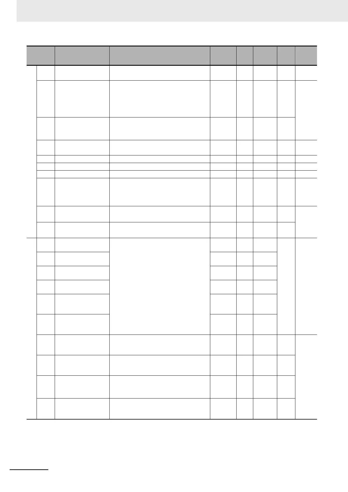
00: Not store frequency data
01: Store frequency data
00
Enabled
P. 7-40
C102
Reset Selection
00: Trip reset at power-on
01: Trip reset at power-off
02: Enabled only during trip (Reset at
power-on)
03: Trip reset only
02
Enabled
P. 5-42
C103
Reset Restart Selec-
tion
00: 0-Hz restart
01: Frequency pull-in restart at shutoff
02: Frequency pull-in restart
00
Enabled
C104
UP/DWN Clear
Selection
00: 0 Hz
01: EEPROM data at power-on
00
Enabled
P. 7-40
C105
EO Gain Setting
50. to 200.
100.
Enabled
%
P. 7-28
C106
AM Gain Setting
50. to 200.
100.
Enabled
%
P. 7-29
C109
AM Bias Setting
0. to 100.
0.
Enabled
%
P. 7-29
C111
1st Overload Warn-
ing Level 2
0.0 Overload warning disabled
0:
0.01 Rated current to 2.00 Rated cur-
rent
Rated
current
1.15
Enabled
A
P. 7-80
C117
Jog Sensitivity Set-
ting
*1
1. to 24.
1.
Enabled
P. 7-61
C118
Jog Carry Sensitivity
Setting
*1
1. to 100.
20.
Enabled
I/O terminal
function
C130
Multi-function Output
11 ON Delay Time
0.0 to 100.0
0.0
Enabled
s
P. 5-55
C131
Multi-function Output
11 OFF Delay Time
0.0
Enabled
C132
Multi-function Output
12 ON Delay Time
0.0
Enabled
C133
Multi-function Output
12 OFF Delay Time
0.0
Enabled
C140
Multi-function Relay
Output ON Delay
Time
0.0
Enabled
C141
Multi-function Relay
Output OFF Delay
Time
0.0
Enabled
C142
Logic Output Signal 1
Selection 1
Same as options for C021 (33 to 35:
LOG1 to LOG3, 63: OPO, and 255: no
cannot be selected.)
00
Enabled
P. 7-85
C143
Logic Output Signal 1
Selection 2
Same as options for C021 (33 to 35:
LOG1 to LOG3, 63: OPO, and 255: no
cannot be selected.)
00
Enabled
C144
Logic Output Signal 1
Operator Selection
00: AND
01: OR
02: XOR
00
Enabled
C145
Logic Output Signal 2
Selection 1
Same as options for C021 (33 to 35:
LOG1 to LOG3, 63: OPO, and 255: no
cannot be selected.)
00
Enabled

Table of Contents

Questions and Answers:

Question and Answer IconNeed help?

Do you have a question about the Omron MX2 Series and is the answer not in the manual?

Omron MX2 Series Specifications

General IconGeneral
Cooling MethodFan cooling
Output Frequency Range0.1 to 400 Hz
Control MethodV/f control, Sensorless vector control
Protection FunctionsOvercurrent, overvoltage, undervoltage, overload, overheating, short circuit
Communication OptionsModbus RTU
Overload Capacity150% for 60 seconds
Braking UnitBuilt-in
Ambient Operating Temperature-10°C to +50°C
EnclosureIP20
Storage Temperature-20°C to +65°C
Humidity5 to 95% RH (non-condensing)
AltitudeUp to 1000m
Power Supply Voltage200-240V AC
Input Voltage3-phase 200-240V AC

Related product manuals