Vectored Interrupt Controller (VIC) 103 May 03, 2004
Philips Semiconductors Preliminary User Manual
LPC2119/2129/2194/2292/2294ARM-based Microcontroller
INTERRUPT SOURCES
Table 54 lists the interrupt sources for each peripheral function. Each peripheral device has one interrupt line connected to the
Vectored Interrupt Controller, but may have several internal interrupt flags. Individual interrupt flags may also represent more
than one interrupt source.
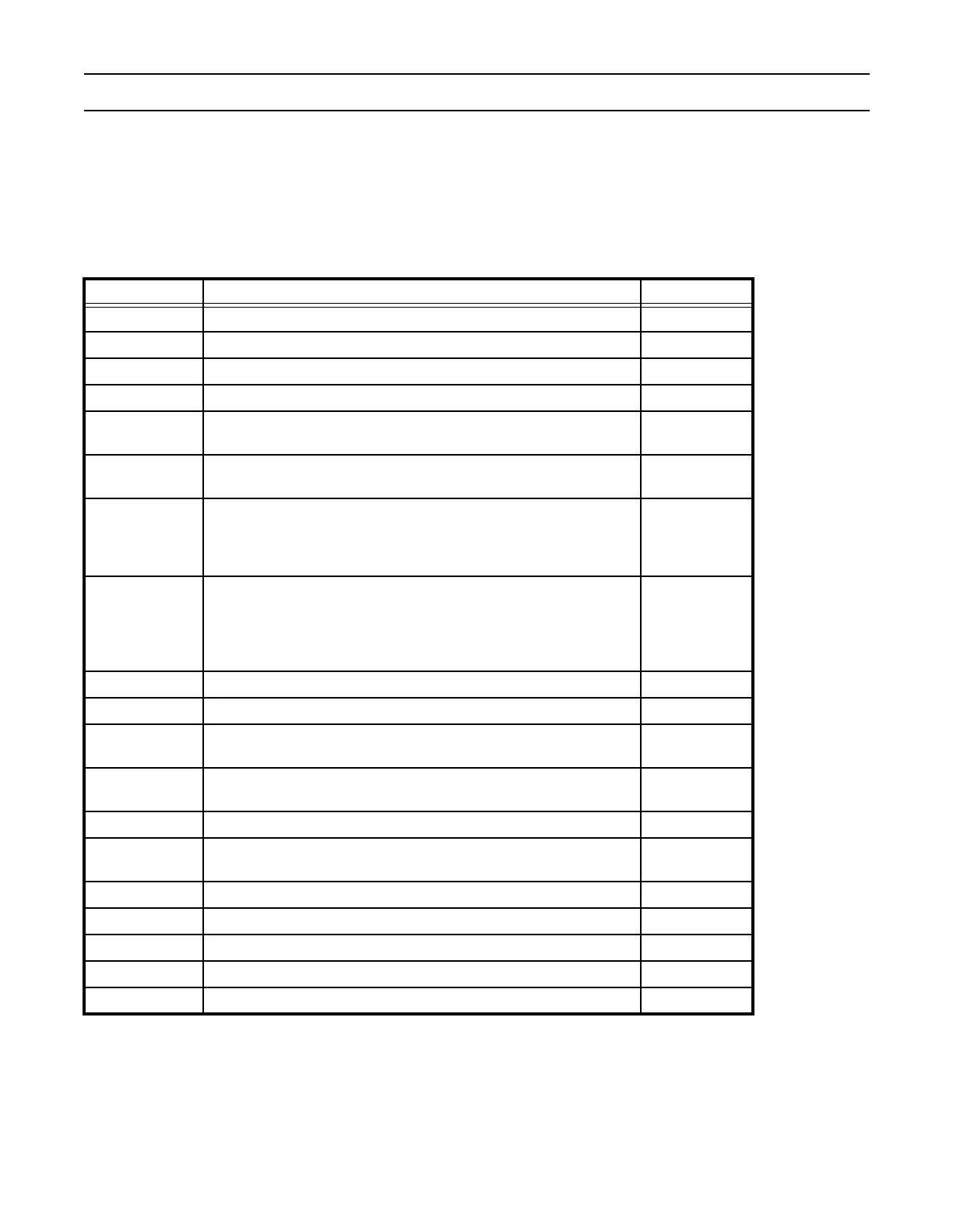
Table 54: Connection of Interrupt Sources to the Vectored Interrupt Controller
Block Flag(s) VIC Channel #
WDT Watchdog Interrupt (WDINT) 0
- Reserved for software interrupts only 1
ARM Core Embedded ICE, DbgCommRx 2
ARM Core Embedded ICE, DbgCommTx 3
TIMER0
Match 0 - 3 (MR0, MR1, MR2, MR3)
Capture 0 - 3 (CR0, CR1, CR2, CR3)
4
TIMER1
Match 0 - 3 (MR0, MR1, MR2, MR3)
Capture 0 - 3 (CR0, CR1, CR2, CR3)
5
UART0
Rx Line Status (RLS)
Transmit Holding Register Empty (THRE)
Rx Data Available (RDA)
Character Time-out Indicator (CTI)
6
UART1
Rx Line Status (RLS)
Transmit Holding Register Empty (THRE)
Rx Data Available (RDA)
Character Time-out Indicator (CTI)
Modem Status Interrupt (MSI)
7
PWM0 Match 0 - 6 (MR0, MR1, MR2, MR3, MR4, MR5, MR6) 8
I
2
C SI (state change) 9
SPI0
SPI Interrupt Flag (SPIF)
Mode Fault (MODF)
10
SPI1
SPI Interrupt Flag (SPIF)
Mode Fault (MODF)
11
PLL PLL Lock (PLOCK) 12
RTC
Counter Increment (RTCCIF)
Alarm (RTCALF)
13
System Control External Interrupt 0 (EINT0) 14
System Control External Interrupt 1 (EINT1) 15
System Control External Interrupt 2 (EINT2) 16
System Control External Interrupt 3 (EINT3) 17
A/D A/D Converter 18