Pulse Width Modulator (PWM) 227 May 03, 2004
Philips Semiconductors Preliminary User Manual
LPC2119/2129/2194/2292/2294ARM-based Microcontroller
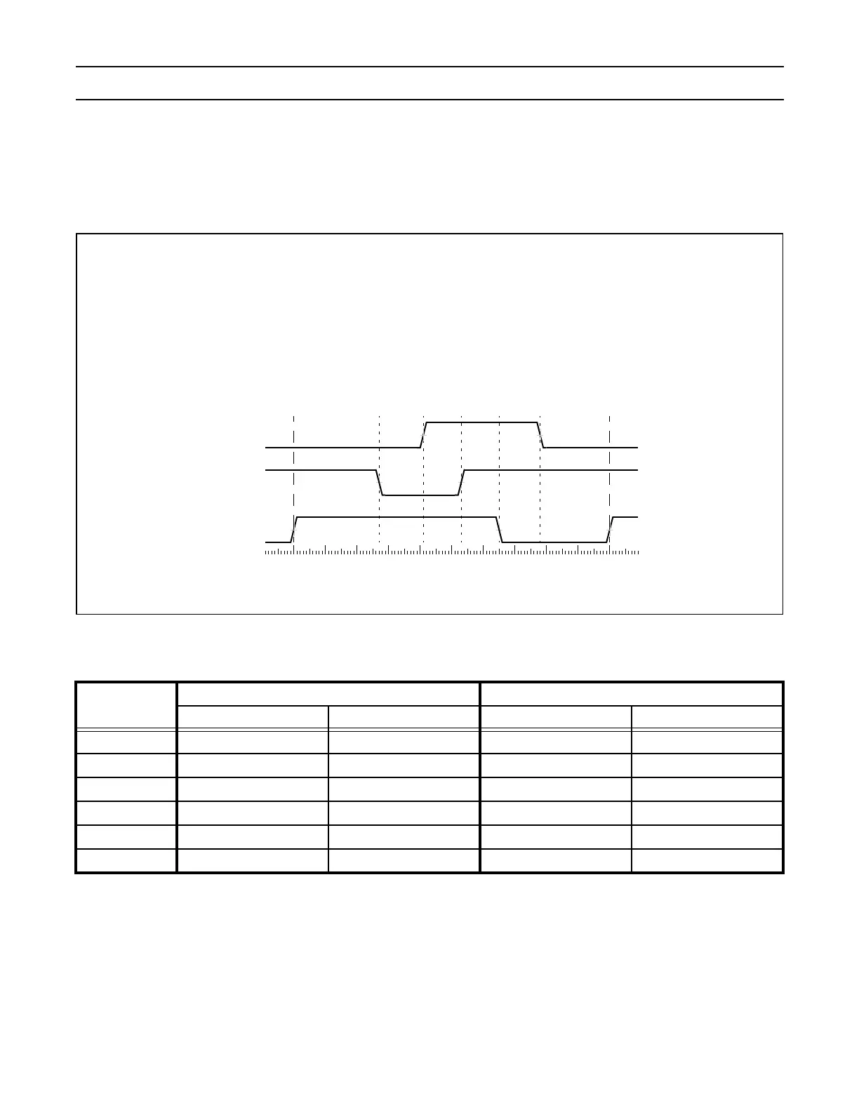
A sample of how PWM values relate to waveform outputs is shown in Figure 43. PWM output logic is shown in Figure 42 that
allows selection of either single or double edge controlled PWM outputs via the muxes controlled by the PWMSELn bits. The
match register selections for various PWM outputs is shown in Table 164. This implementation supports up to N-1 single edge
PWM outputs or (N-1)/2 double edge PWM outputs, where N is the number of match registers that are implemented. PWM types
can be mixed if desired.
Figure 43: Sample PWM waveforms
Notes:
1. Identical to single edge mode in this case since Match 0 is the neighboring match register. Essentially, PWM1 cannot be a
double edged output.
2. It is generally not advantageous to use PWM channels 3 and 5 for double edge PWM outputs because it would reduce the
number of double edge PWM outputs that are possible. Using PWM 2, PWM4, and PWM6 for double edge PWM outputs
provides the most pairings.
Table 164: Set and Reset inputs for PWM Flip-Flops
PWM
Channel
Single Edge PWM (PWMSELn = 0) Double Edge PWM (PWMSELn = 1)
Set by Reset by Set by Reset by
1 Match 0 Match 1 Match 0
1
Match 1
1
2 Match 0 Match 2 Match 1 Match 2
3 Match 0 Match 3 Match 2
2
Match 3
2
4 Match 0 Match 4 Match 3 Match 4
5 Match 0 Match 5 Match 4
2
Match 5
2
6 Match 0 Match 6 Match 5 Match 6
1007841270
PWM4
53
• The timer is configured for PWM mode.
• Match 0 is configured to reset the timer/counter
when a match event occurs.
• Control bits PWMSEL2 and PWMSEL4 are set.
(counter is reset)
PWM5
65
PWM2
• The Match register values are as follows:
MR0= 100(PWM rate)
MR1= 41, MR2 = 78(PWM2 output)
MR3= 53, MR4 = 27(PWM4 output)
MR5= 65(PWM5 output)
The waveforms below show a single PWM cycle and demonstrate PWM outputs under the following conditions: