UART1 153 May 03, 2004
Philips Semiconductors Preliminary User Manual
LPC2119/2129/2194/2292/2294ARM-based Microcontroller
REGISTER DESCRIPTION
*Reset Value refers to the data stored in used bits only. It does not include reserved bits content.
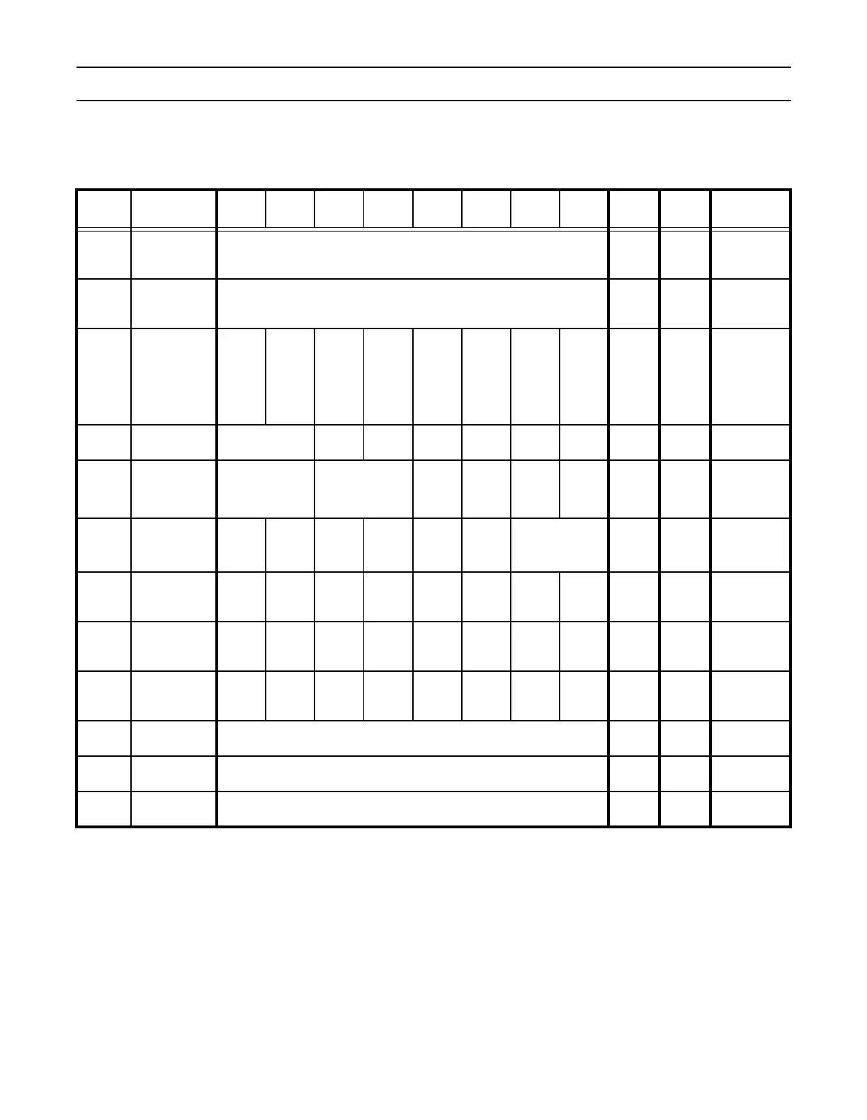
UART1 contains twelve 8-bit registers as shown in Table 87. The Divisor Latch Access Bit (DLAB) is contained in U1LCR7 and
enables access to the Divisor Latches.
Table 87: UART1 Register Map
Name Description BIT 7 BIT 6 BIT 5 BIT 4 BIT 3 BIT 2 BIT 1 BIT 0 Access
Reset
Value*
Address
U1RBR
Receiver
Buffer
Register
MSB READ DATA LSB RO
un-
defined
0xE0010000
DLAB = 0
U1THR
Transmit
Holding
Register
MSB WRITE DATA LSB WO NA
0xE0010000
DLAB = 0
U1IER
Interrupt
Enable
Register
0000
Enable Modem
Status
Interrupt
Enable Rx Line
Status
Interrupt
Enable THRE
Interrupt
Enable Rx Data
Available
Interrupt
R/W 0
0xE0010004
DLAB = 0
U1IIR
Interrupt ID
Register
FIFOs Enabled 0 0 IIR3 IIR2 IIR1 IIR0 RO 0x01 0xE0010008
U1FCR
FIFO
Control
Register
Rx Trigger Reserved -
Tx FIFO
Reset
Rx FIFO
Reset
FIFO
Enable
WO 0 0xE0010008
U1LCR
Line Control
Register
DLAB
Set
Break
Stick
Parity
Even
Parity
Select
Parity
Enable
Number
of Stop
Bits
Word Length
Select
R/W 0 0xE001000C
U1MCR
Modem
Control
Register
000
Loop
Back
0 0 RTS DTR R/W 0 0xE0010010
U1LSR
Line Status
Register
Rx
FIFO
Error
TEMT THRE BI FE PE OE DR RO 0x60 0xE0010014
U1MSR
Modem
Status
Register
DCD RI DSR CTS
Delta
DCD
Trailing
Edge
RI
Delta
DSR
Delta
CTS
RO 0 0xE0010018
U1SCR
Scratch Pad
Register
MSB LSB R/W 0 0xE001001C
U1DLL
Divisor Latch
LSB
MSB LSB R/W 0
0xE0010000
DLAB = 1
U1DLM
Divisor Latch
MSB
MSB LSB R/W 0
0xE0010004
DLAB = 1