Timer0 and Timer1 221 May 03, 2004
Philips Semiconductors Preliminary User Manual
LPC2119/2129/2194/2292/2294ARM-based Microcontroller
EXAMPLE TIMER OPERATION
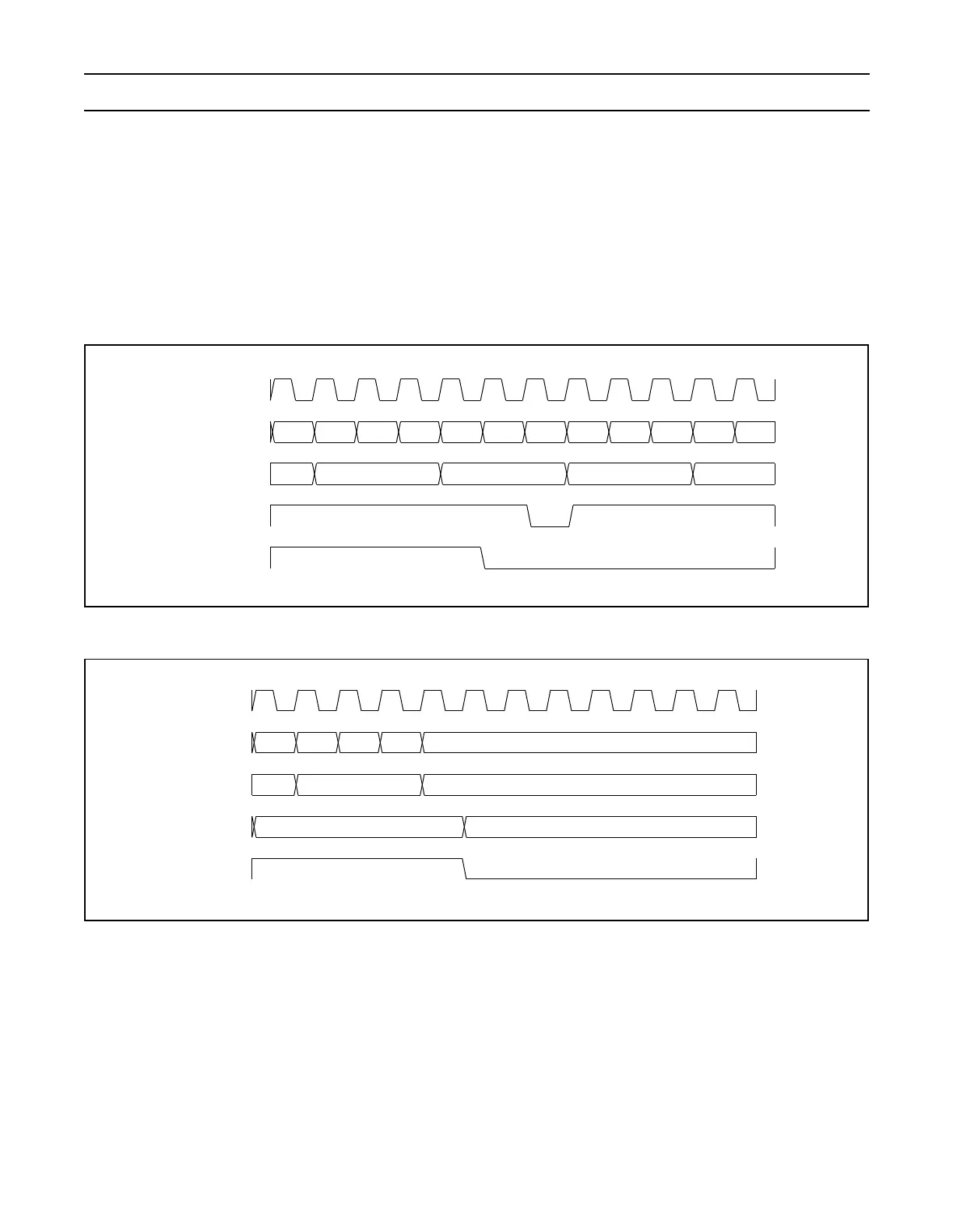
Figure 39 shows a timer configured to reset the count and generate an interrupt on match. The prescaler is set to 2 and the match
register set to 6. At the end of the timer cycle where the match occurs, the timer count is reset. This gives a full length cycle to
the match value. The interrupt indicating that a match occurred is generated in the next clock after the timer reached the match
value.
Figure 40 shows a timer configured to stop and generate an interrupt on match. The prescaler is again set to 2 and the match
register set to 6. In the next clock after the timer reaches the match value, the timer enable bit in TCR is cleared, and the interrupt
indicating that a match occurred is generated.
Figure 39: A timer cycle in which PR=2, MRx=6, and both interrupt and reset on match are enabled.
Figure 40: A timer cycle in which PR=2, MRx=6, and both interrupt and stop on match are enabled.
Prescale Counter
Timer Counter
Timer Counter
Reset
Interrupt
56401
012012012012
pclk
Prescale Counter
Timer Counter
TCR[0]
(Counter Enable)
Interrupt
012
564
01
02
pclk