Pin Connect Block 132 May 03, 2004
Philips Semiconductors Preliminary User Manual
LPC2119/2129/2194/2292/2294ARM-based Microcontroller
Pin Function Select Register Values
The PINSEL registers control the functions of device pins as shown below. Pairs of bits in these registers correspond to specific
device pins.
The direction control bit in the IO0DIR/IO1DIR register is effective only when the GPIO function is selected for a pin. For other
functions, direction is controlled automatically. Each derivative typically has a different pinout and therefore a different set of
functions possible for each pin. Details for a specific derivative may be found in the appropriate data sheet.
27:25
Controls the number of pins among P3.23/A23/XCLK and P3.22:2/A2.22:2 that are address lines:
000 if
BOOT1:0=11
at Reset, 111
otherwise
000 = None 100 = A11:2 are address lines.
001 = A3:2 are address lines. 101 = A15:2 are address lines.
010 = A5:2 are address lines. 110 = A19:2 are address lines.
011 = A7:2 are address lines. 111 = A23:2 are address lines.
31:28 Reserved. -
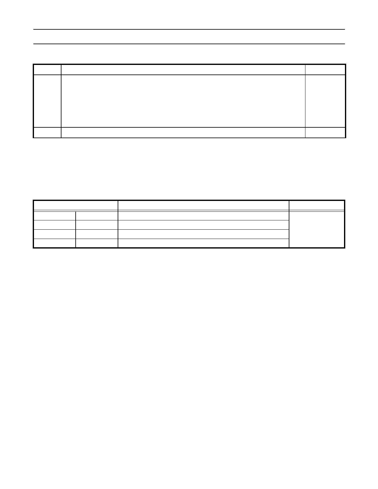
Table 65: Pin Function Select Register Bits
Pinsel0 and Pinsel1 Values Function Value after Reset
0 0 Primary (default) function, typically GPIO Port
00
0 1 First alternate function
1 0 Second alternate function
11Reserved
Table 64: Pin Function Select Register 2 for LPC2292/2294 (PINSEL2 - 0xE002C014)
PINSEL2 Description Reset Value