UART1 155 May 03, 2004
Philips Semiconductors Preliminary User Manual
LPC2119/2129/2194/2292/2294ARM-based Microcontroller
UART1 Interrupt Enable Register (U1IER - 0xE0010004 when DLAB = 0)
The U1IER is used to enable the four interrupt sources.
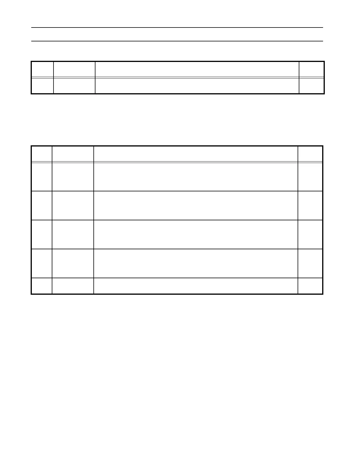
Table 91: UART1 Divisor Latch MSB Register (U1DLM - 0xE0010004 when DLAB = 1)
U1DLM Function Description
Reset
Value
7:0
Divisor Latch
MSB Register
The UART1 Divisor Latch MSB Register, along with the U1DLL register, determines the
baud rate of the UART1.
0
Table 92: UART1 Interrupt Enable Register Bit Descriptions (U1IER - 0xE0010004 when DLAB = 0)
U1IER Function Description
Reset
Value
0
RBR Interrupt
Enable
0: Disable the RDA interrupt.
1: Enable the RDA interrupt.
U1IER0 enables the Receive Data Available interrupt for UART1. It also controls the
Receive Time-out interrupt.
0
1
THRE Interrupt
Enable
0: Disable the THRE interrupt.
1: Enable the THRE interrupt.
U1IER1 enables the THRE interrupt for UART1. The status of this interrupt can be read
from U1LSR5.
0
2
Rx Line Status
Interrupt Enable
0: Disable the Rx line status interrupts.
1: Enable the Rx line status interrupts.
U1IER2 enables the UART1 Rx line status interrupts. The status of this interrupt can be
read from U1LSR[4:1].
0
3
Modem Status
Interrupt Enable
0: Disable the modem interrupt.
1: Enable the modem interrupt.
U1IER3 enables the modem interrupt. The status of this interrupt can be read from
U1MSR[3:0].
0
7:4 Reserved
Reserved, user software should not write ones to reserved bits. The value read from a
reserved bit is not defined.
NA