UART1 162 May 03, 2004
Philips Semiconductors Preliminary User Manual
LPC2119/2129/2194/2292/2294ARM-based Microcontroller
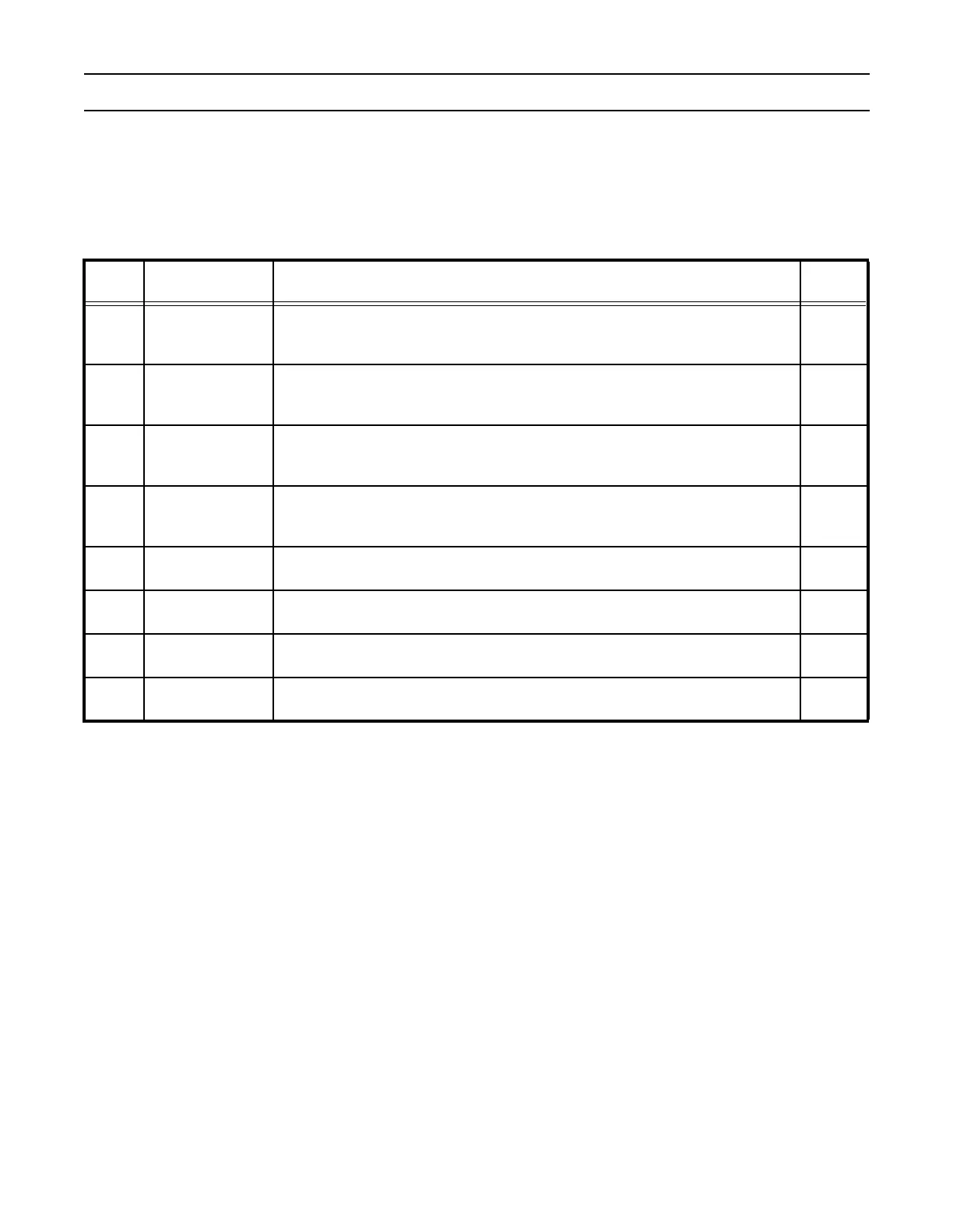
UART1 Modem Status Register (U1MSR - 0x0xE0010018)
The U1MSR is a read-only register that provides status information on the modem input signals. U1MSR3:0 is cleared on U1MSR
read. Note that modem signals have no direct affect on UART1 operation, they facilitate software implementation of modem
signal operations.
Table 99: UART1 Modem Status Register Bit Descriptions (U1MSR - 0x0xE0010018)
U1MSR Function Description
Reset
Value
0 Delta CTS
0: No change detected on modem input, CTS.
1: State change detected on modem input, CTS.
Set upon state change of input CTS. Cleared on an U1MSR read.
0
1 Delta DSR
0: No change detected on modem input, DSR.
1: State change detected on modem input, DSR.
Set upon state change of input DSR. Cleared on an U1MSR read.
0
2 Trailing Edge RI
0: No change detected on modem input, RI.
1: Low-to-high transition detected on RI.
Set upon low to high transition of input RI. Cleared on an U1MSR read.
0
3Delta DCD
0: No change detected on modem input, DCD.
1: State change detected on modem input, DCD.
Set upon state change of input DCD. Cleared on an U1MSR read.
0
4CTS
Clear To Send State. Complement of input signal CTS. This bit is connected to
U1MCR[1] in modem loopback mode.
0
5DSR
Data Set Ready State. Complement of input signal DSR. This bit is connected to
U1MCR[0] in modem loopback mode.
0
6RI
Ring Indicator State. Complement of input RI. This bit is connected to U1MCR[2] in
modem loopback mode.
0
7 DCD
Data Carrier Detect State. Complement of input DCD. This bit is connected to
U1MCR[3] in modem loopback mode.
0