Pin Connect Block 133 May 03, 2004
Philips Semiconductors Preliminary User Manual
LPC2119/2129/2194/2292/2294ARM-based Microcontroller
BOOT CONTROL ON 144-PIN PACKAGE
In the 144-pin package only, the state of the BOOT1:0 pins, while RESET is low, controls booting and initial operation. Internal
pullups in the receivers ensure high state if a pin is left unconnected. Board designers can connect weak pulldown resistors
(~10 k:) or transistors that drive low while RESET
is low, to these pins to select among the following options:
Note that if an application enables the Watchdog Timer to Reset the part if it’s not serviced, transistors driven by RESET
should
not be used.
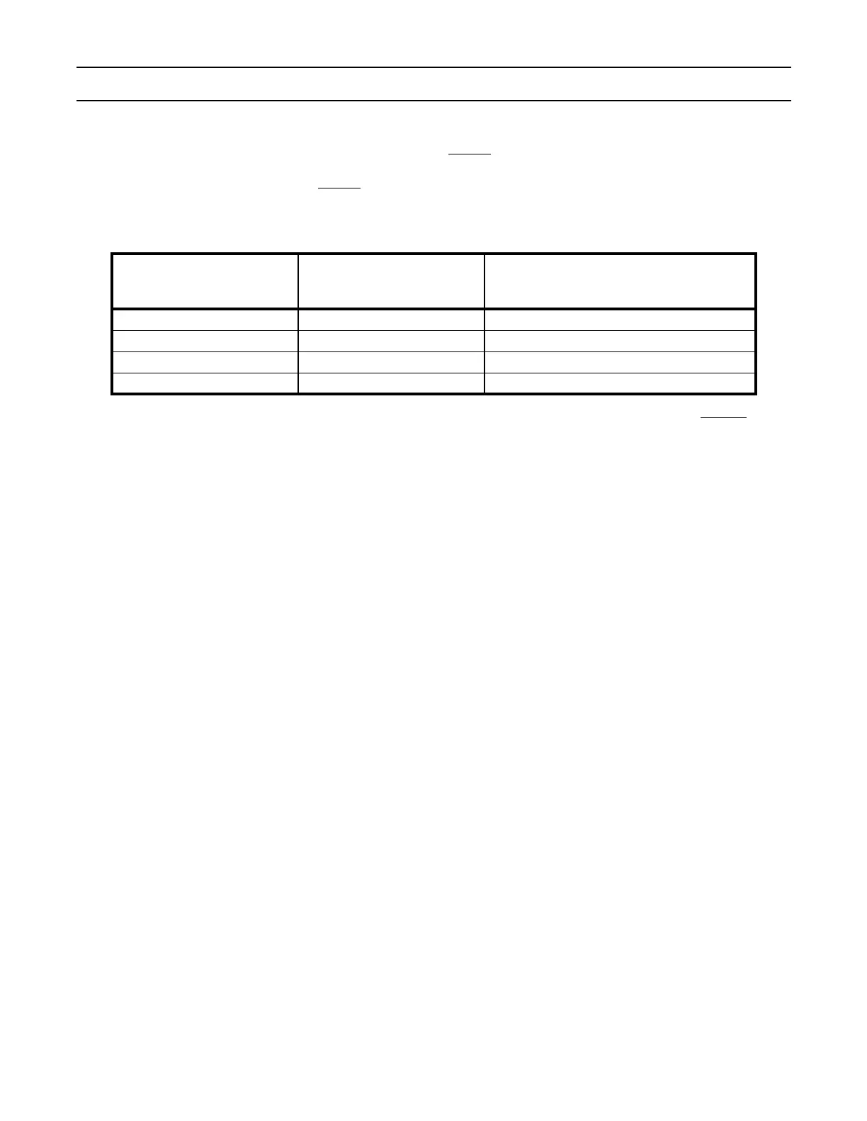
Table 66: Boot Control on BOOT1:0
BOOT1
(latched from P2.27/D27 on
Reset pin rising edge only)
BOOT0
(latched from P2.26/D26 on
Reset pin rising edge only)
Boot from
0 0 8-bit memory on CS0
0 1 16-bit memory on CS0
1 0 32-bit memory on CS0
1 1 Internal Flash Memory