Pulse Width Modulator (PWM) 230 May 03, 2004
Philips Semiconductors Preliminary User Manual
LPC2119/2129/2194/2292/2294ARM-based Microcontroller
REGISTER DESCRIPTION
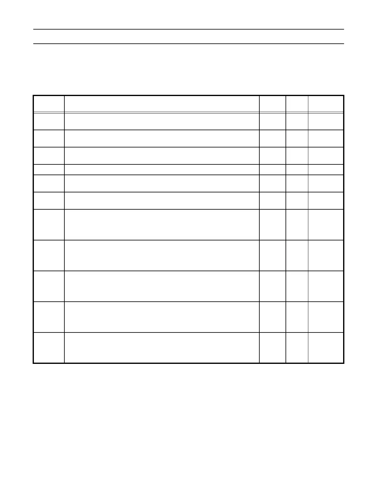
The PWM function adds new registers and registers bits as shown in Table 166 below.
Table 166: Pulse Width Modulator Register Map
Name Description Access
Reset
Value*
Address
PWMIR
PWM Interrupt Register. The IR can be written to clear interrupts. The IR can
be read to identify which of the possible interrupt sources are pending.
R/W 0 0xE0014000
PWMTCR
PWM Timer Control Register. The TCR is used to control the Timer Counter
functions. The Timer Counter can be disabled or reset through the TCR.
R/W 0 0xE0014004
PWMTC
PWM Timer Counter. The 32-bit TC is incremented every PR+1 cycles of pclk.
The TC is controlled through the TCR.
RW 0 0xE0014008
PWMPR PWM Prescale Register. The TC is incremented every PR+1 cycles of pclk. R/W 0 0xE001400C
PWMPC
PWM Prescale Counter. The 32-bit PC is a counter which is incremented to the
value stored in PR. When the value in PR is reached, the TC is incremented.
R/W 0 0xE0014010
PWMMCR
PWM Match Control Register. The MCR is used to control if an interrupt is
generated and if the TC is reset when a Match occurs.
R/W 0 0xE0014014
PWMMR0
PWM Match Register 0. MR0 can be enabled through MCR to reset the TC,
stop both the TC and PC, and/or generate an interrupt when it matches the TC.
In addition, a match between MR0 and the TC sets all PWM outputs that are in
single-edge mode, and sets PWM1 if it is in double-edge mode.
R/W 0 0xE0014018
PWMMR1
PWM Match Register 1. MR1 can be enabled through MCR to reset the TC,
stop both the TC and PC, and/or generate an interrupt when it matches the TC.
In addition, a match between MR1 and the TC clears PWM1 in either single-
edge mode or double-edge mode, and sets PWM2 if it is in double-edge mode.
R/W 0 0xE001401C
PWMMR2
PWM Match Register 2. MR2 can be enabled through MCR to reset the TC,
stop both the TC and PC, and/or generate an interrupt when it matches the TC.
In addition, a match between MR2 and the TC clears PWM2 in either single-
edge mode or double-edge mode, and sets PWM3 if it is in double-edge mode.
R/W 0 0xE0014020
PWMMR3
PWM Match Register 3. MR3 can be enabled through MCR to reset the TC,
stop both the TC and PC, and/or generate an interrupt when it matches the TC.
In addition, a match between MR3 and the TC clears PWM3 in either single-
edge mode or double-edge mode, and sets PWM4 if it is in double-edge mode.
R/W 0 0xE0014024
PWMMR4
PWM Match Register 4. MR4 can be enabled through MCR to reset the TC,
stop both the TC and PC, and/or generate an interrupt when it matches the TC.
In addition, a match between MR4 and the TC clears PWM4 in either single-
edge mode or double-edge mode, and sets PWM5 if it is in double-edge mode.
R/W 0 0xE0014040