System Control Block 80 May 03, 2004
Philips Semiconductors Preliminary User Manual
LPC2119/2129/2194/2292/2294ARM-based Microcontroller
Procedure for Determining PLL Settings
If a particular application uses the PLL, its configuration may be determined as follows:
1. Choose the desired processor operating frequency (cclk). This may be based on processor throughput requirements,
need to support a specific set of UART baud rates, etc. Bear in mind that peripheral devices may be running from a lower
clock than the processor (see the VPB Divider description in this chapter).
2. Choose an oscillator frequency (F
osc
). cclk must be the whole (non-fractional) multiple of F
osc
.
3. Calculate the value of M to configure the MSEL bits. M = cclk / F
osc
. M must be in the range of 1 to 32. The value written
to the MSEL bits in PLLCFG is M - 1 (see Table 28).
4. Find a value for P to configure the PSEL bits, such that F
cco
is within its defined frequency limits. F
cco
is calculated using
the equation given above. P must have one of the values 1, 2, 4, or 8. The value written to the PSEL bits in PLLCFG is 00
for P = 1; 01 for P = 2; 10 for P = 4; 11 for P = 8 (see Table 27).
PLL Example
System design asks for F
osc
= 10 MHz and requires cclk = 60 MHz.
Based on these specifications, M = cclk / F
osc
= 60 MHz / 10 MHz = 6. Consequenty, M-1 = 5 will be written as PLLCFG 4:0.
Value for P can be derived from P = F
cco
/ (cclk * 2), using condition that F
cco
must be in range of 156 MHz to 320 MHz. Assuming
the lowest allowed frequency for F
cco
= 156 MHz, P = 156 MHz / (2*60 MHz) = 1.3. The highest F
cco
frequency criteria produces
P = 2.67. The only solution for P that satisfies both of these requirements and is listed in Table 27 is P = 2. Therefore, PLLCFG
6:5 = 1 will be used.
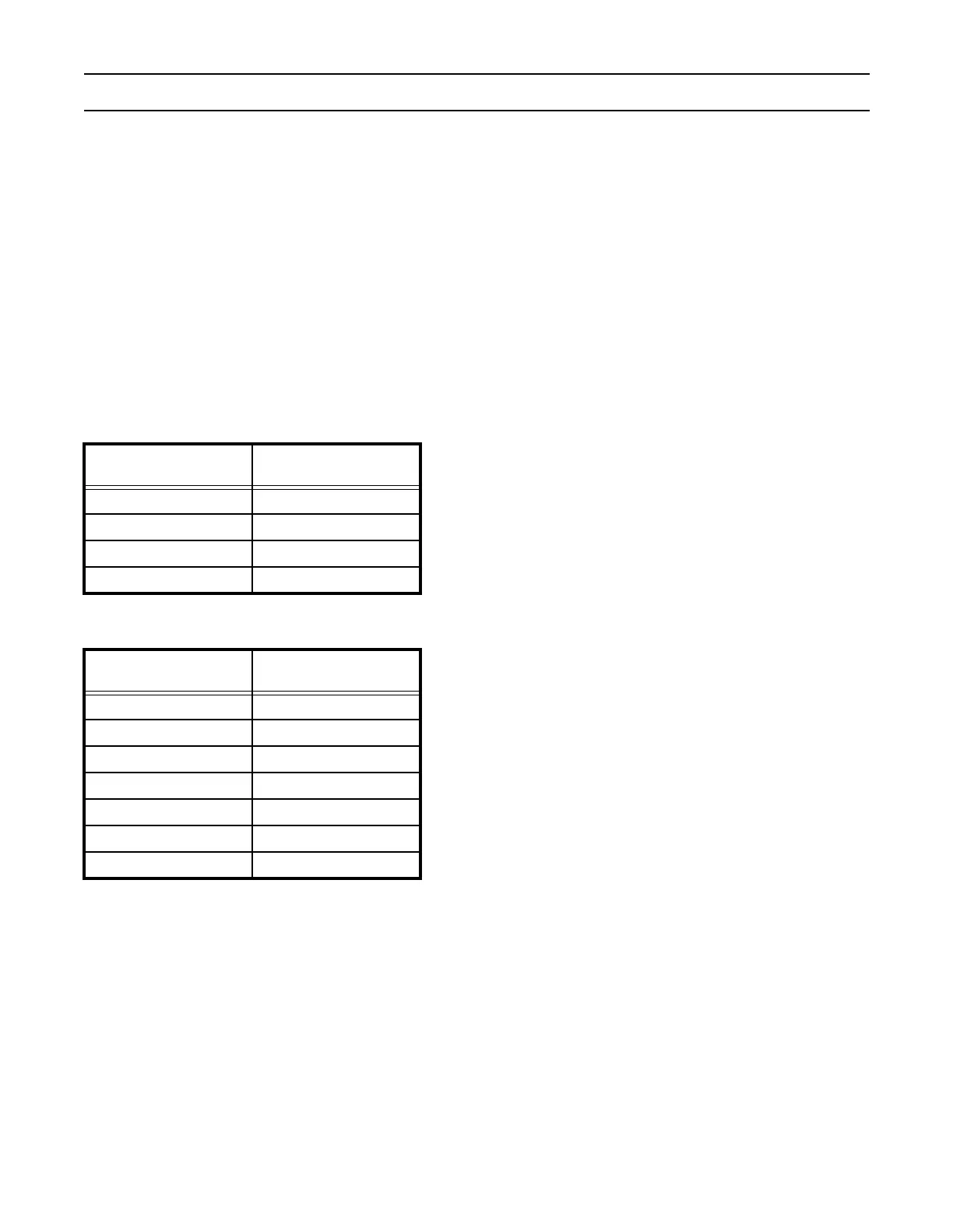
Table 27: PLL Divider Values
PSEL Bits
(PLLCFG bits 6:5)
Value of P
00 1
01 2
10 4
11 8
Table 28: PLL Multiplier Values
MSEL Bits
(PLLCFG bits 4:0)
Value of M
00000 1
00001 2
00010 3
00011 4
... ...
11110 31
11111 32