Real Time Clock 243 May 03, 2004
Philips Semiconductors Preliminary User Manual
LPC2119/2129/2194/2292/2294ARM-based Microcontroller
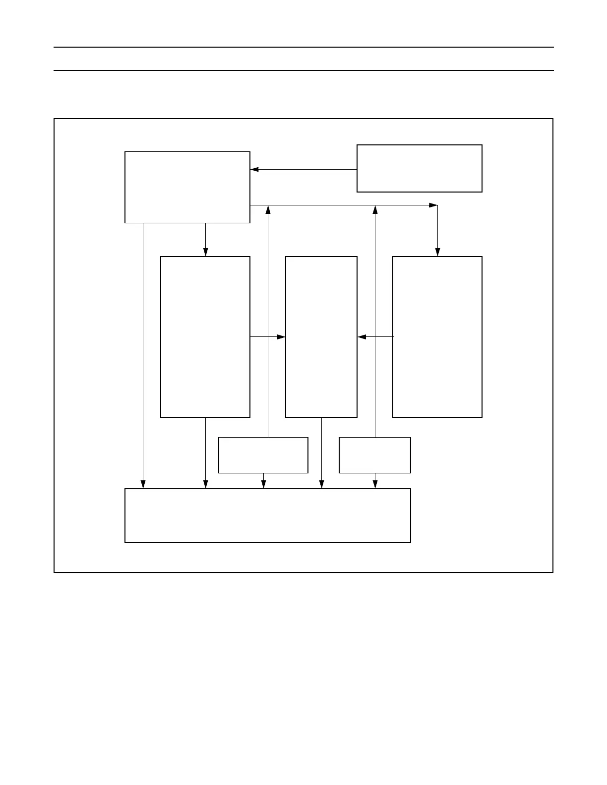
ARCHITECTURE
Figure 44: RTC block diagram
REGISTER DESCRIPTION
The RTC includes a number of registers. The address space is split into four sections by functionality. The first eight addresses
are the Miscellaneous Register Group. The second set of eight locations are the Time Counter Group. The third set of eight
locations contain the Alarm Register Group. The remaining registers control the Reference Clock Divider.
The Real Time Clock includes the register shown in Table 176. Detailed descriptions of the registers follow.
Clock
Generator
clk32k
Clk1 CCLK
Interrupt Generator
Counter
Enables
Counter Increment
Interrupt Enable
Alarm Mask
Register
Alarm
Registers
ComparatorsTime
Counters
Reference Clock Divider
(Prescaler)
Strobe