Timer0 and Timer1 217 May 03, 2004
Philips Semiconductors Preliminary User Manual
LPC2119/2129/2194/2292/2294ARM-based Microcontroller
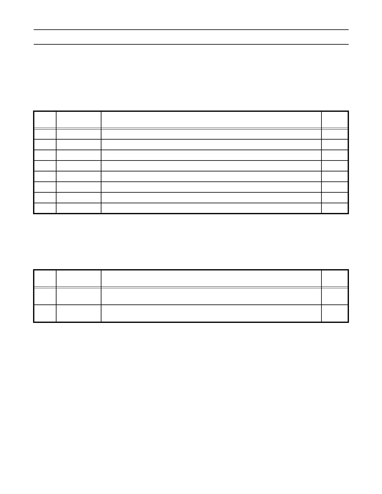
Interrupt Register (IR: TIMER0 - T0IR: 0xE0004000; TIMER1 - T1IR: 0xE0008000)
The Interrupt Register consists of four bits for the match interrupts and four bits for the capture interrupts. If an interrupt is
generated then the corresponding bit in the IR will be high. Otherwise, the bit will be low. Writing a logic one to the corresponding
IR bit will reset the interrupt. Writing a zero has no effect.
Timer Control Register (TCR: TIMER0 - T0TCR: 0xE0004004; TIMER1 - T1TCR: 0xE0008004)
The Timer Control Register (TCR) is used to control the operation of the Timer Counter.
Timer Counter (TC: TIMER0 - T0TC: 0xE0004008; TIMER1 - T1TC: 0xE0008008)
The 32-bit Timer Counter is incremented when the Prescale Counter reaches its terminal count. Unless it is reset before reaching
its upper limit, the TC will count up through the value 0xFFFFFFFF and then wrap back to the value 0x00000000. This event
does not cause an interrupt, but a Match register can be used to detect an overflow if needed.
Prescale Register (PR: TIMER0 - T0PR: 0xE000400C; TIMER1 - T1PR: 0xE000800C)
The 32-bit Prescale Register specifies the maximum value for the Prescale Counter.
Table 158: Interrupt Register (IR: TIMER0 - T0IR: 0xE0004000; TIMER1 - T1IR: 0xE0008000)
IR Function Description
Reset
Value
0 MR0 Interrupt Interrupt flag for match channel 0. 0
1 MR1 Interrupt Interrupt flag for match channel 1. 0
2 MR2 Interrupt Interrupt flag for match channel 2. 0
3 MR3 Interrupt Interrupt flag for match channel 3. 0
4 CR0 Interrupt Interrupt flag for capture channel 0 event. 0
5 CR1 Interrupt Interrupt flag for capture channel 1 event. 0
6 CR2 Interrupt Interrupt flag for capture channel 2 event. 0
7 CR3 Interrupt Interrupt flag for capture channel 3 event. 0
Table 159: Timer Control Register (TCR: TIMER0 - T0TCR: 0xE0004004; TIMER1 - T1TCR: 0xE0008004)
TCR Function Description
Reset
Value
0 Counter Enable
When one, the Timer Counter and Prescale Counter are enabled for counting. When
zero, the counters are disabled.
0
1 Counter Reset
When one, the Timer Counter and the Prescale Counter are synchronously reset on the
next positive edge of pclk. The counters remain reset until TCR[1] is returned to zero.
0