Function description
Operating Manual PNOZ s30
1001715-EN-19
| 34
} Logic operations
The results of the switch functions F1 … F9 and the area operations F2-F3 … F8-F9 can
be linked together logically (AND, OR). The following operations can be assigned:
F2 AND F3 (F2 ∧ F3)
F4 AND F5 (F4 ∧ F5)
F1 AND F6-F7 (F1 ∧ F6-F7)
F1 AND F8-F9 (F1 ∧ F8-F9)
F6 OR F7 (F6 ∨ F7)
F8 OR F9 (F8 ∨ F9)
F1 OR F2-F3 (F1 ∨ F2-F3)
F1 OR F4-F5 (F1 ∨ F4-F5)
} Analogue output
The semiconductor output OUT 4 (Y35) can be configured as 0 – 20 mA or 4 – 20 mA
analogue output.
} Error output
Every output can be configured as an error output.
Error: Output switched off
No error: Output switched on
} Output OFF
Every output can be switched off permanently
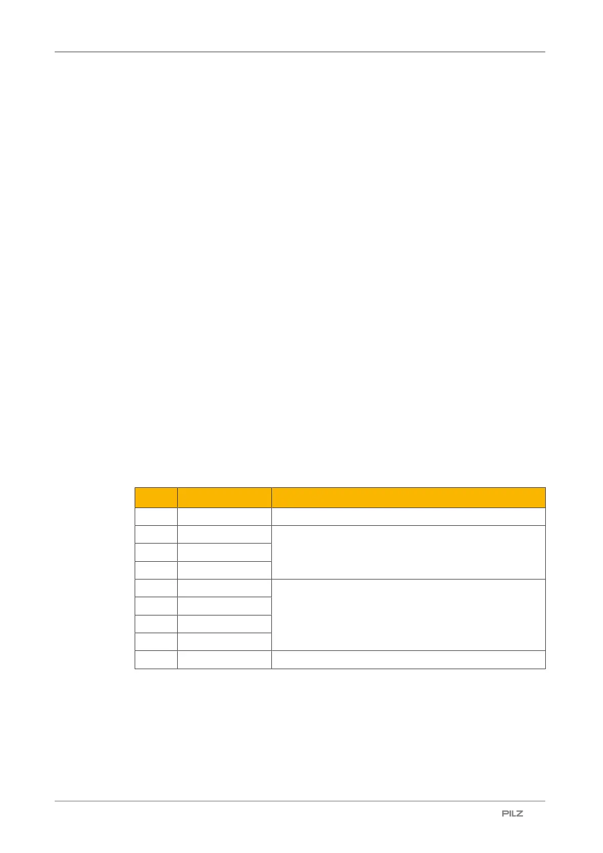
Overview output assignments
Every assignment has a unique number.
The assignment options are available:
No. On the display Description
0 Off
1 F1 Individual switch functions
…
9 F9
10 F2 - F3 Speed range
11 F4 - F5
12 F6 - F7
13 F8 - F9
14 Err Error output

 Loading...


