Wiring
Operating Manual PNOZ s30
1001715-EN-19
| 45
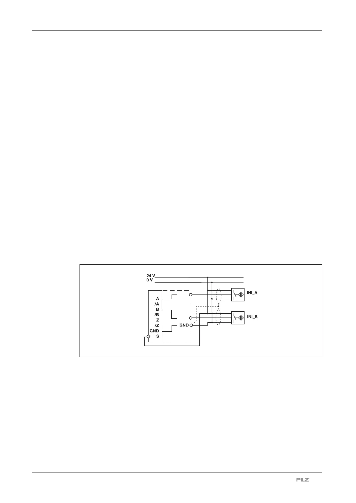
7.4 Connection of proximity switches
The following proximity switch combinations can be connected:
} A: pnp, B: pnp
} A: npn, B: npn
} A: pnp, B: npn
} A: npn, B: pnp
Connection for 2 proximity switches with reduced diagnostics:
} A: pnp, B: pnp
When connecting proximity switches please note:
} Proximity switches can either be connected to terminals In1, In2 and GND or to tracks A
and B plus GND on the RJ45 socket.
} Track S should be used to monitor the supply voltage (see drawing). A permitted voltage
range can be entered in the menu.
} Connect the proximity switch to 24 V DC of the power supply.
} When connecting the proximity switches, please refer to the chapter entitled "EMC-com-
pliant wiring"
} Invalid signals may occur with cable lengths >50 m. In this case we recommend that you
connect a resistor between the signal lines, as shown in the diagrams.
Special features when connecting 2 proximity switches with reduced diagnostics:
} The cables for connecting the proximity switches must be laid separately.
} The supply voltage to the proximity switches must be monitored, via track S for example.

 Loading...


