Function description
Operating Manual PNOZ s30
1001715-EN-19
| 39
5.5 Input device types
5.5.1 Proximity switch
} The following proximity switches can be used:
– pnp
– npn
} The values stated under Safety characteristic data [ 108] apply only when using prox-
imity switches that are implemented as N/O contacts.
} The proximity switches must be fitted so that at least one is always activated. In other
words, the proximity switches must be fitted so that the recorded signals always overlap.
} The cable used to connect the proximity switches must be shielded (see connection dia-
grams in the chapter entitled "EMC-compliant wiring").
} The supply voltage of the proximity switches should be monitored via track S.
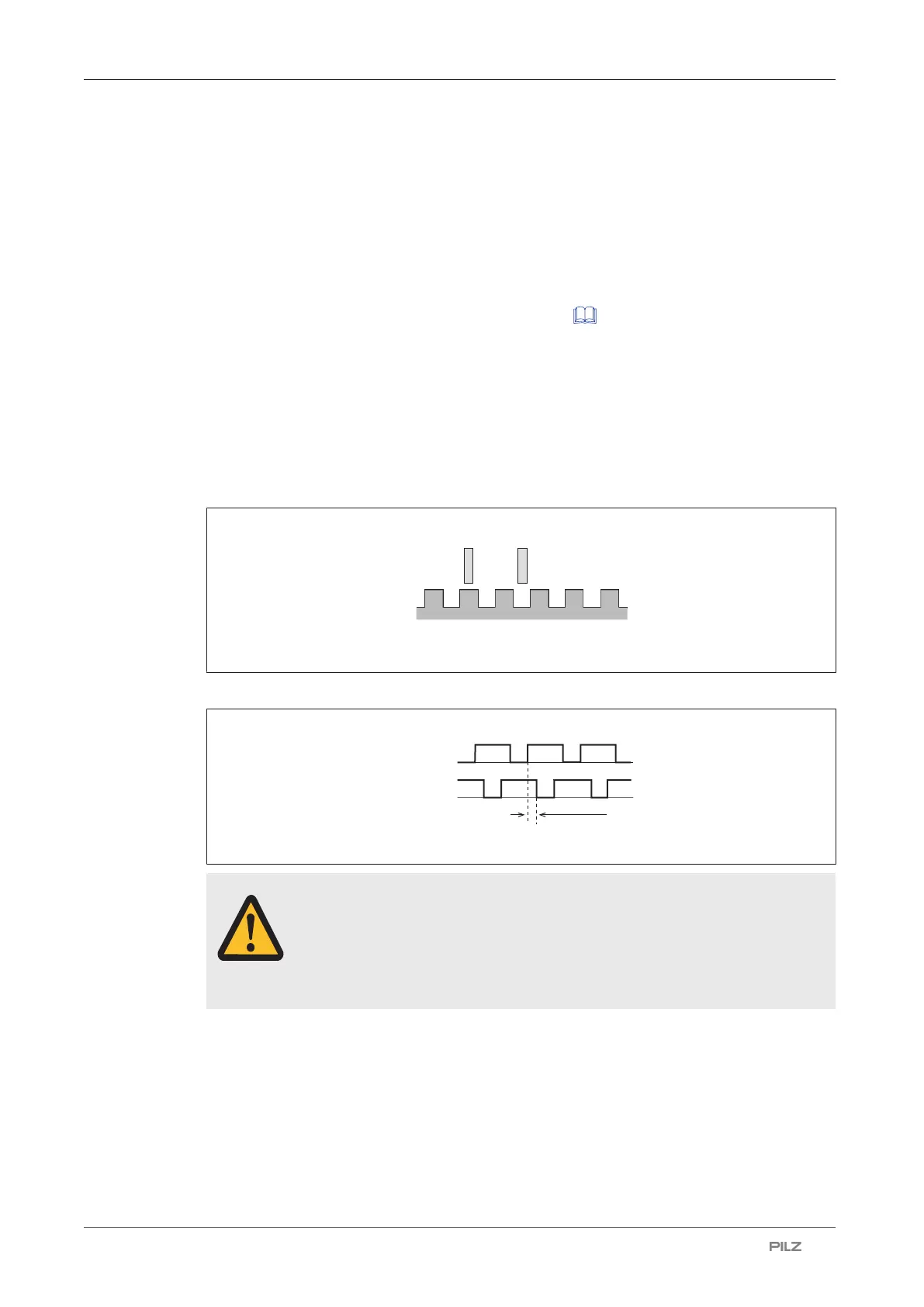
Proximity switch assembly:
Example pnp – pnp:
Proximity switch 1
Proximity switch 2
Energised
De-energised
Energised
De-energised
> 1 % of the period length
CAUTION!
Appropriate installation measures should be taken to prevent a foreign body
coming between the signal encoder and the proximity switch. If not, the for-
eign body could cause invalid signals.
} Please note the values stated in the technical details
} The maximum frequency of the used encoders must be entered for a full configuration
("Encoder" menu → "Track AB" → "Track AB fmax" / "Track Z" → "Track Z fmax").

 Loading...


