18 - MCM260X - Manuale d’uso
ENC2
15
ENC3
17
ENC4
19
A
B
Z
+
SUPPLY
ENC1
13
16 18 20
14
35 36 37
34
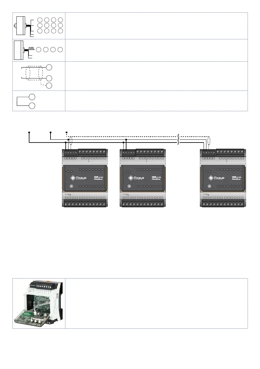
ENCODER
Use push-pull encoders only
Max frequency 80KHz
CNT2
15
CNT3
17
CNT4
19
+
-
SUPPLY
CNT1
13
PNP input
Max frequency 80KHz
CANH (B)
CAN
RS485
CANL (A)
(C)
Shield / Schermo
23
22
24
Field bus:
22: CANH / RS485+
23: CANL / RS485-
24: C GND for CANbus and Modbus RTU
23
CANL (A)
25
Terminator of the communication line in manual mode.
To permanently insert the 120 ohm termination resistance through wiring,
connect clip 25 to clip 23 using a wire.
4.2 Connection to the communication line
Below is the diagram for the connection of more than one MCM260X to a RS485 line or CAN network.
.16
.15
.14
.13
.12
.11
.10
.9
.8
.7
.6
.5
.4
.3
.2
.1
RUN
COM
.16
.15
.14
.13
.12
.11
.10
.9
.8
.7
.6
.5
.4
.3
.2
.1
RUN
COM
.16
.15
.14
.13
.12
.11
.10
.9
.8
.7
.6
.5
.4
.3
.2
.1
RUN
COM
13 14 15 16 17 201918 21 22 23 24 25
CAN H
(B)
CAN L
(A)
(C)
Q-I D
I-I D
Q.9
Q.1 0
Q.1 2
Q.1 3
Q.1 4
Q.1 5
Q.1 6
+
1 2
3
54 6 987
10
11
12
B-T
+V
VDC
12. ..24V
Q.1
Q.2
Q.3
Q.4
Q.5
Q.6
Q.7
Q.8
MCM 260X
1AD
13 14 15 16 17 201918 21 22 23 24 25
CAN H
(B)
CAN L
(A)
(C)
Q-I D
I-I D
Q.9
Q.1 0
Q.1 2
Q.1 3
Q.1 4
Q.1 5
Q.1 6
+
1 2
3
54 6 987
10
11
12
B-T
+V
VDC
12. ..24V
Q.1
Q.2
Q.3
Q.4
Q.5
Q.6
Q.7
Q.8
MCM 260X
1AD
13 14 15 16 17 201918 21 22 23 24 25
CAN H
(B)
CAN L
(A)
(C)
Q-I D
I-I D
Q.9
Q.1 0
Q.1 2
Q.1 3
Q.1 4
Q.1 5
Q.1 6
+
1 2
3
54 6 987
10
11
12
B-T
+V
VDC
12. ..24V
Q.1
Q.2
Q.3
Q.4
Q.5
Q.6
Q.7
Q.8
MCM 260X
1AD
RS485+
CANH
RS485-
CANL
REF
5 Device SET-UP
To be used as I/O module, the MCM260X needs a configuration procedure to set the correct parameters
that manage the communication. This configuration procedure may be run through the terminal
(display and keys) or via the MyPixsys app. Below is the procedure to change the parameters via the
terminal.
5.1 Numeric indicators (internal display)
The internal display, in combination with the pushbuttons §, ¶ and | is
used to configure the module. In the power on phase the display shows the
firmware version while in normal operation, in the absence of anomalies, the
display remains off. In case of anomalies it shows the number of the active
error. In the configuration phase it shows the parameter being entered.