10
10.13
9924874 R02 - 2014 RZR XP / XP 4 1000 Service Manual
© Copyright 2013 Polaris Industries Inc.
SWITCHES / CONTROLS
Brake Light Switch
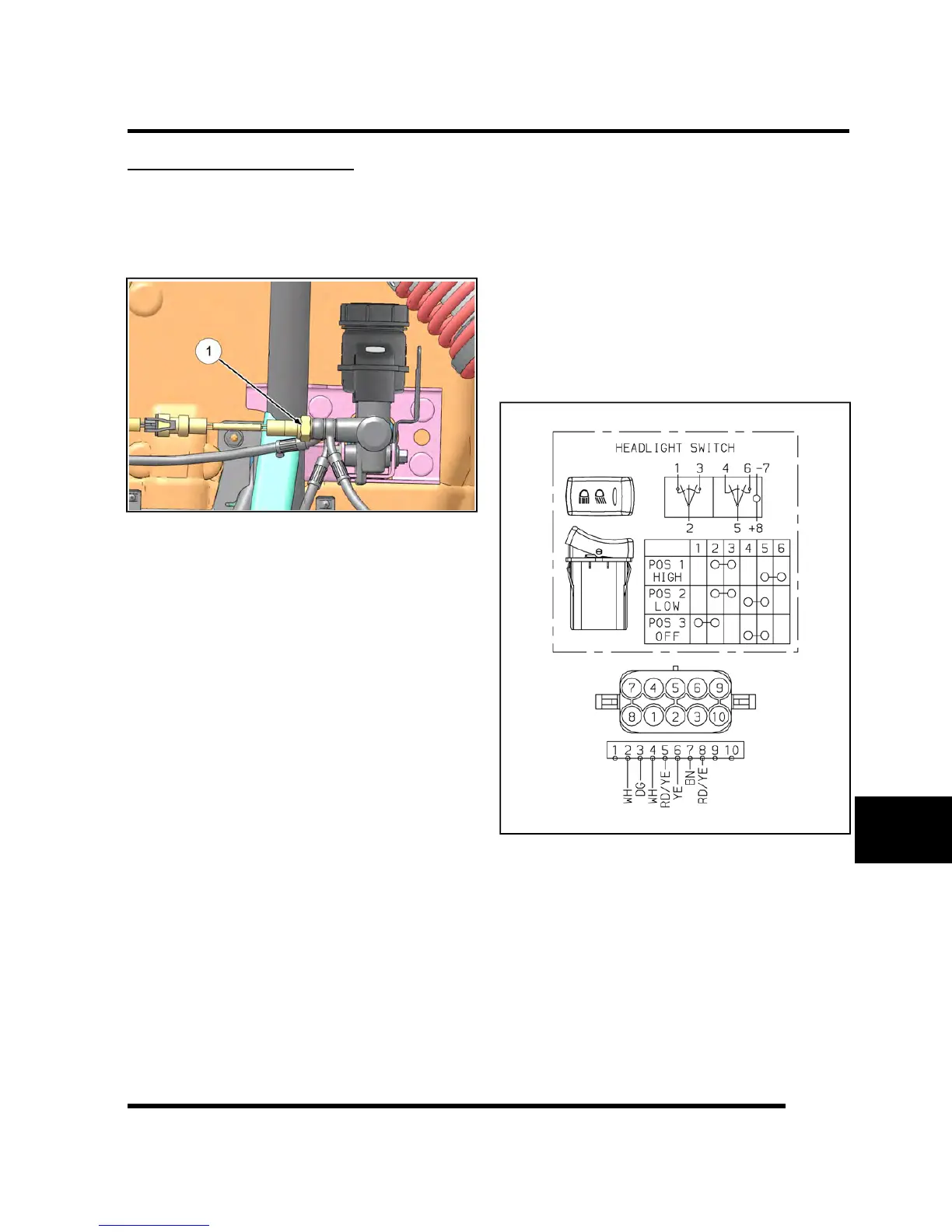
1. The brake light switch (Item 1) is located on the front
brake line banjo bolt of the master cylinder. The
brake switch can be accessed through the left front
wheel well opening.
2. Disconnect wire harness from switch and connect an
ohmmeter across switch contacts. The reading
should be infinite (OL).
3. Apply the brake and check for continuity. If there is
no continuity or if resistance is greater than 0.5
ohms, clean the switch terminals. Re-test and
replace switch if necessary.
4. For switch replacement, refer to Chapter 9 “Brakes”.
Headlamp Switch
1. Disconnect the headlamp switch harness by
depressing the connector locks and pulling on the
connector. Do not pull on the wiring.
2. Test between the 3 sets of outputs (OFF / LOW /
HIGH). If any of the tests fail, replace headlamp
switch assembly.
• Move the switch to HIGH. There should be
continuity between switch pins 2 and 3; 5 and 6.
• Move the switch to LOW. There should be
continuity between switch pins 2 and 3; 4 and 5.
• Move the switch to OFF. There should be
continuity between switch pins 1 and 2; 4 and 5.
NOTE: Pins 7 and 8 provide power and ground
to light the switch lamp.
ELECTRICAL

 Loading...