10
10.31
9924874 R02 - 2014 RZR XP / XP 4 1000 Service Manual
© Copyright 2013 Polaris Industries Inc.
WARNING
Never start the engine with an ammeter connected in
series. Damage to the meter or meter fuse will result.
Do not run test for extended period of time.
Do not run test with high amperage accessories.
1. Using an inductive amperage metering device, (set
to DC amps) connect to the negative battery cable.
2. With engine off, key switch and lights in the on
position, the ammeter should read negative amps
(battery discharge).
3. Shift transmission into park and start the engine.
With the engine running at idle, observe meter
readings.
4. Increase engine RPM while observing ammeter and
tachometer. Note the RPM at which the battery starts
to charge (ammeter indication is positive).
5. With lights and other electrical loads off, the “break
even” point should occur at approximately 1500 RPM
or lower.
6. With the engine running, turn the lights on and
depress the brake pedal to keep brake lights on.
7. Repeat test, observing ammeter and tachometer.
With lights on, charging should occur at or below
2000 RPM.
Charging System Stator (Alternator) Tests
Three tests can be performed using a multi-meter to
determine the condition of the stator (alternator).
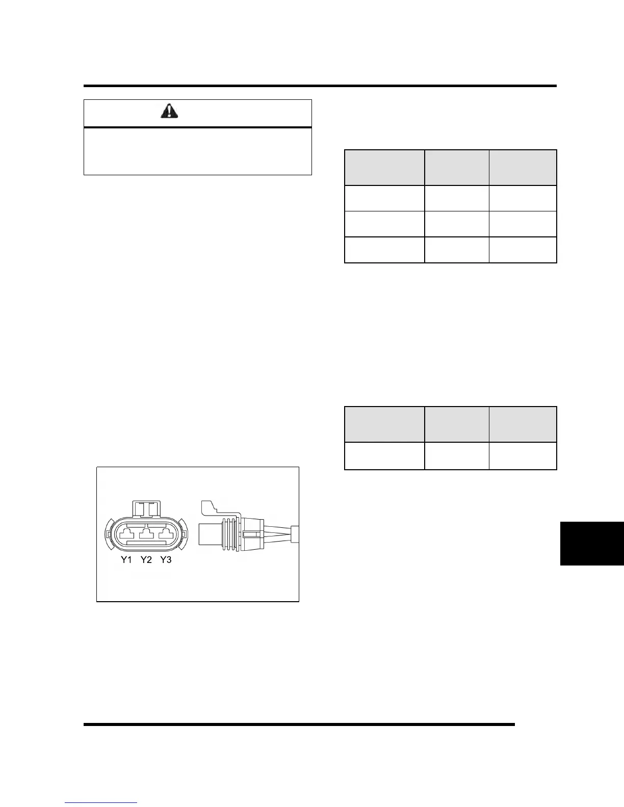
TEST 1: Resistance Value of Each Stator Leg
1. Measure the resistance value of each of the three
stator legs: Y1 to Y2, Y1 to Y3, and Y2 to Y3. Each
test should measure: 0.07 - 0.13 Ω
TEST
CONNECT
METER
LEADS TO:
OHMS
READING
Battery Charge
Coil
Y1 to Y2 0.07 - 0.13 Ω
Battery Charge
Coil
Y1 to Y3 0.07 - 0.13 Ω
Battery Charge
Coil
Y2 to Y3 0.07 - 0.13 Ω
NOTE: If there are any significant variations in
ohm readings between the three legs it is an
indication that one of the stator legs may be
weak or failed.
TEST 2: Resistance Value of Each Stator Leg to
Ground
2. Measure the resistance value of each of the stator
legs to ground: Y1 to Ground, Y2 to Ground, Y3 to
Ground.
3. Each test should measure: Open Line (OL)
TEST
CONNECT
METER
LEADS TO:
OHMS
READING
Battery Charge
Coil
Y1, Y2, or Y3
to Ground
Open Line
(Infinity)
NOTE: Any measurement other than Infinity
(open) will indicate a failed or shorted stator leg.
TEST 3: Measure AC Voltage Output of Each
Stator Leg at Charging RPM
4. Set the selector dial to measure AC Voltage.
5. Start the engine and let it idle.
6. While holding the engine at a specified RPM,
separately measure the voltage across each ‘leg’ of
the stator by connecting the meter leads to the wires
leading from the alternator (Y1 to Y2, Y1 to Y3, Y2 to
Y3).
7. Refer to the following table for approximate AC
Voltage readings according to RPM. Test each leg at
the specified RPM in the table.
ELECTRICAL

 Loading...