10.24
9924874 R02 - 2014 RZR XP / XP 4 1000 Service Manual
© Copyright 2013 Polaris Industries Inc.
COOLING SYSTEM
Fan Control Circuit Operation / Testing
Power is supplied to the fan via the Orange/Black wire
when the relay is ON. The ground path for the fan motor
is through the Brown harness wire. Refer to “RELAYS”
later in this chapter for more information on fan functions.
CAUTION
Keep hands away from fan blades during operation.
Serious personal injury could result.
NOTE: The fan may not function or operation may
be delayed if coolant level is low or if air is trapped in
the cooling system. Be sure cooling system is full
and purged of air.
Fan Control Circuit Bypass Test
1. Disconnect harness from coolant temperature
sensor on the engine cylinder head (see Chapter 4).
2. With the transmission in Park, start the engine. After
a few seconds, the fan should start running and the
“Check Engine” indicator should display on the
instrument cluster. This indicates all other
components are working properly.
3. If the fan does not run or runs slowly, check the fan
motor wiring, ground, motor condition, circuit breaker
and mechanical relay for proper operation. Repair or
replace as necessary. If the fan runs with the sensor
harness disconnected, but will not turn on when the
engine is hot, check the coolant temperature sensor
and connector terminals.
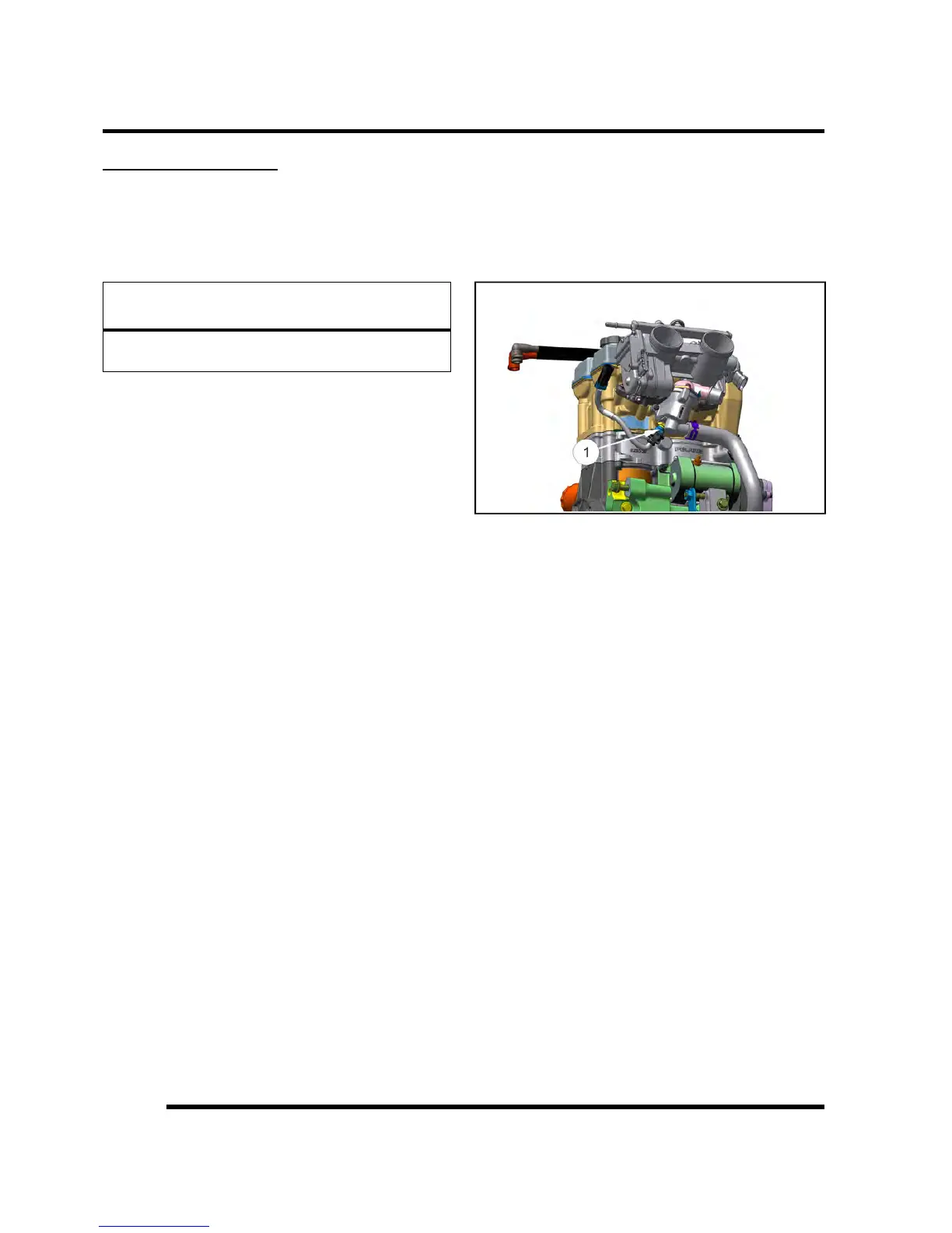
Engine Coolant Temperature Sensor (ECT)
Overview
Mounted in the thermostat housing, the engine
temperature sensor (Item 1) measures coolant
temperature. The engine temperature sensor is a
Negative Temperature Coefficient (NTC) type sensor, as
the temperature increases the resistance decreases.
Coolant passes through the thermostat housing and by
the sensor probe, varying a resistance reading which is
relayed to the ECU. This signal is processed by the ECU
and compared to its programming for determining the
fuel and ignition requirements during operation. The ECU
also uses this signal to determine when to activate the
cooling fan during operation.
ELECTRICAL

 Loading...