61
Slide Scanner Repair Manual Calibration and Adjustments
Focus (Non-Uniformity) Adjustment
1. Setup the dual trace oscilloscope as follows:
• Time Base - 200 usec/div
• Amplitude- 500 mv/div
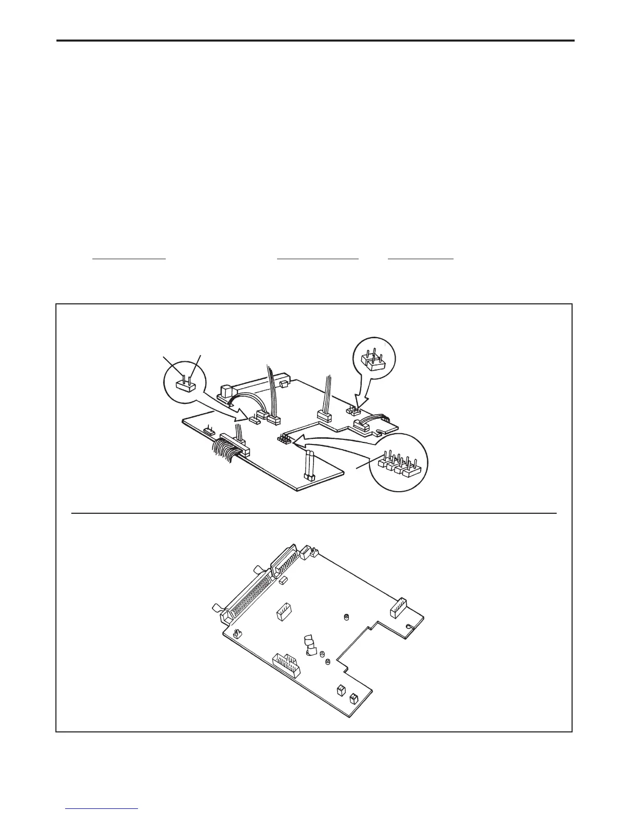
2. Connect the dual trace oscilloscope to the applicable main controller board test points
(Figure 3-5) as follows:
Note: Figure 3-6 displays the RGB raw output of the VSP before the focus target
is inserted in the light path.
Oscilloscope SS35/SS35 ES SS35 PLUS
External (Ext) BNC J7 - pin 2 LSYNC
Channel 1 input BNC J2 - pin 8 ADIN
Figure 3-5. Main controller PC board test points
SS35/SS35 ES
SS35 PLUS
GND
LSYNC
1
2
Video
Out
5
8
6
Not Used
J 1
J 2
J 3
J 5
J 8
J 4
J 6
J 9
J 10
1
3
7
(GND's - Pins 1, 3, 5, 7)
4
2
J 7
J10
J12
J14
J13
J8
J6
J5
SCSI
Fuse
LYSNC
J3
AGND
J1
ADIN
 Loading...