94
Slide Scanner Repair Manual Parts Replacement
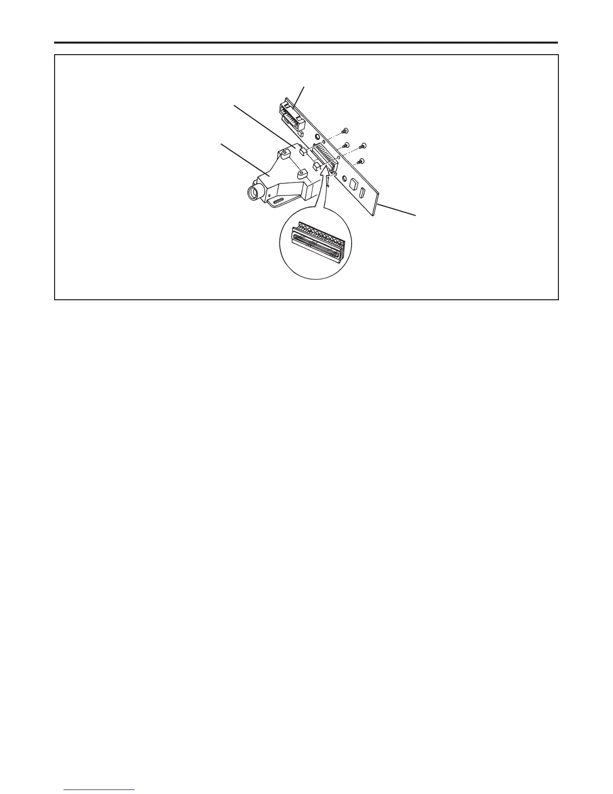
Figure 4-15. Replacing CCD sensor PC board
9. Install the replacement CCD sensor board onto the CCD mounting block .
Notes: • Use a diagonal pattern tightening method when installing the CCD sensor PC
board onto the CCD mounting block. Tightening the screws seat the CCD
surface exactly parallel to the mounting block.
• Recommendation for SS35/SS35 ES repair. The repair technician should
disconnect the SCSI ribbon cable from the controller PC board and then
reconnect a used cable assembly (taken from an old non-repairable slide
scanner or, fabricated in-house) to the controller PC board. Using a separate
cable prevents the weight of the back panel/cable assembly from holding the
controller PC board tightly against the top of the CCD board while tilt
adjustments are made.
10. Slightly loosen the four (4) mounting screws so that the CCD sensor PC board can be
adjusted for tilt later in this procedure.
11. Reconnect the CCD board ribbon cable to connector J1.
12. Connect the power cord to the slide scanner.
CAUTION
Make sure that you do not touch any live power connections
on the back panel while it's hanging loose from the base plate.
CCD
CCD
Sensor PC Board
Lens Block Assembly
J1
CCD Mounting Block
 Loading...