95
Slide Scanner Repair Manual Parts Replacement
13. Connect the slide scanner to the host computer and run the Stand-Alone Motion test
that is part of the LabVIEW IPT test.
14. Using the tilt number test result (from the Motion test) make a fine adjustment (up or down)
to the CCD sensor PC board to achieve correct tilt. Tilt in the clockwise direction increases
the angle and tilt in the counter clockwise direction decrease tilt.
Notes: • After the adjustment is made, tighten down two (2) of the screws that
secures the CCD sensor PC board to its mounting block. Once the final
tilt adjustment is made, tighten all four (4) screws that secures the CCD
sensor PC board to its mounting block.
• Focus and magnification may also have to be adjusted.
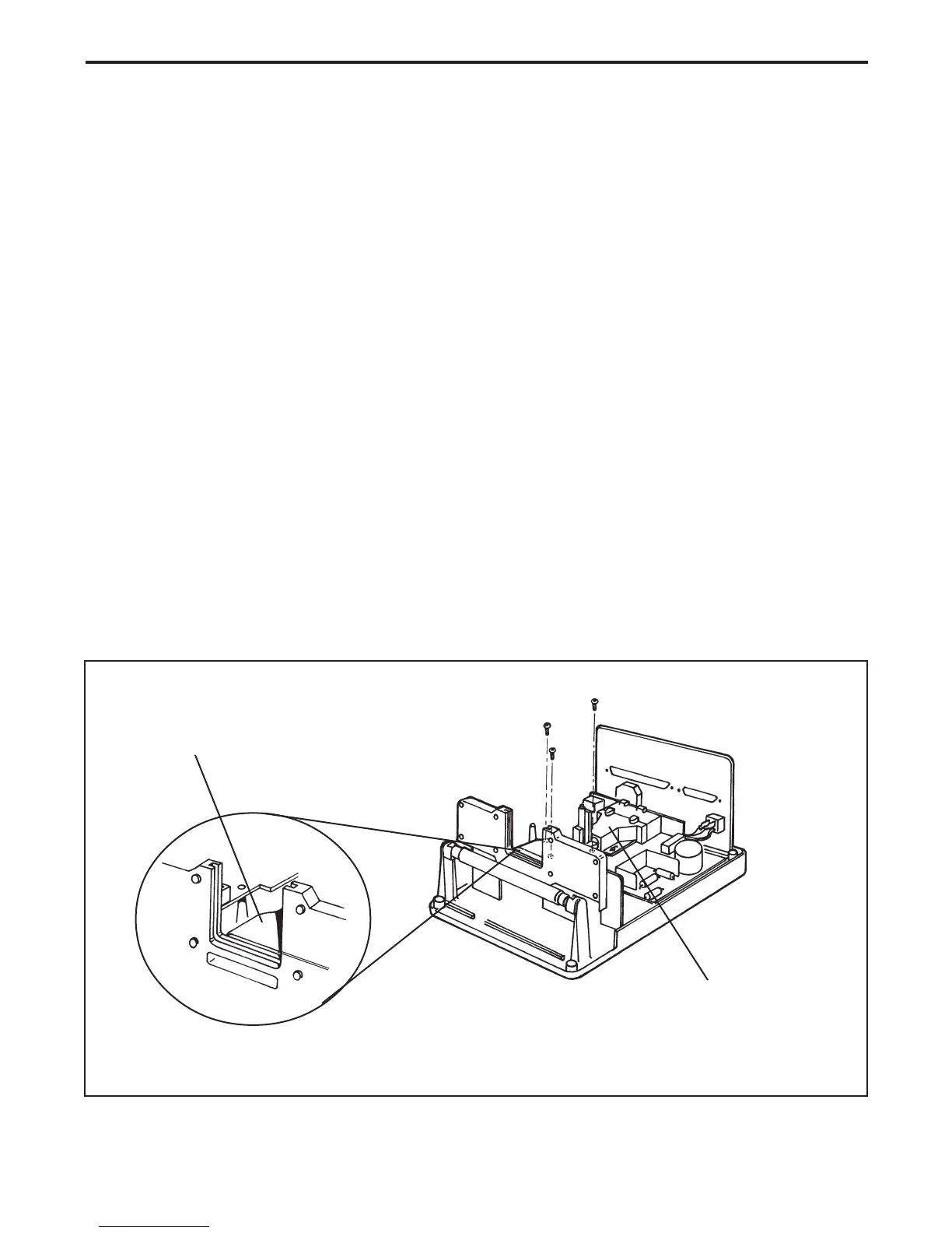
15. If applicable, after the slide scanner passes all the IPT tests reinstall the light tunnel.
Note: Make sure that there is a 1mm clearance between the face of the light tunnel
and the holder assembly (Figure 4-16).
16. Disconnect the power cord and the SCSI cables.
17. Reinstall the back panel.
18. Reinstall the top housing.
Figure 4-16. Light tunnel clearance
1 mm
Light Tunnel
Holder Assembly
Chassis Assembly
 Loading...