349
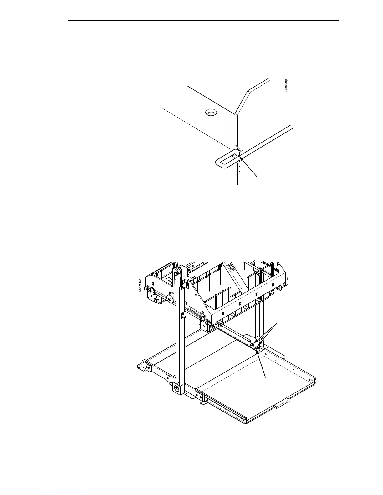
13. Insert the bent end of the retainer wire into the card cage notch. (Figure
75.)
Figure 75. Locking the Cable Routing Guide Retainer Wire
14. Pull the paper tray out until the holes in the rails permit access to the M3
buttonhead screws. (Figure 76.)
15. Loosen one turn—do not remove—the M3 screws securing the vertical
rails to the stacker base. Each rail is secured by two screws. (Figure 76.)
Figure 76. The Lower Screws in the Vertical Rails
Card Cage Notch
M3x6 Buttonhead Screw
(Two on each rail)
Access Hole in
Tray Rail