55
Trinity F90+ user manual
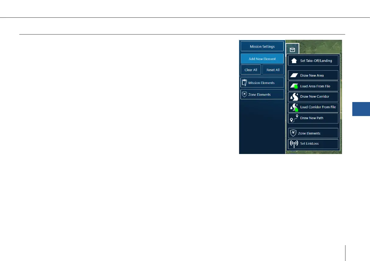
Add new element
Add a new element by clicking one of the following buttons:
Set Take-Off/Landing: Location and settings of Take-Off/Landing and retransition
can be individually adjusted afterwards.
Draw New Area: The ight area is created by dening the corners of an area. Each
click on the map denes a corner of the area. The orange highlighted circle repre-
sents the highlighted corner. To move a corner it must be selected.
Load Area From File: A .kml or .shp le can be imported into QBase. The ight
area is automatically created based on the le.
Draw New Corridor: The corridor is created by dening the points of a polyline.
The orange highlighted circle represents the selected point. To move a point it
must be selected.
Load Corridor From File: A .kml or .shp le can be imported into QBase. The corri-
dor is automatically created based on the le.
Draw New Path: The path is created by dening waypoints through a click on the map.
Zone Elements: The zone element is created by dening the corners of an area. Each click on the map denes a corner of the
area. The orange highlighted circle represents the selected corner. To move a corner it must be selected.
Link Loss: (chapter 7.3):
By default, the Link Loss Loiter Circle is equal to the retransition circle. You can set it separately using this
element.
QBase – Ground Control Station
7