XLi EDGE QubicaAMF Pinspotter
Section 3 Page 3-12 Rev. Date: 10/2016
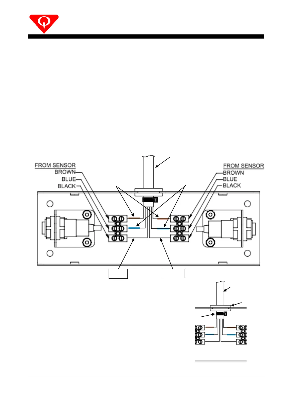
Connect the wires with the ‘Blue’ heat shrink tubing to the terminals that the
‘Blue’ wire of the optical emitters/sensors is secured to. One wire to each
terminal strip.
Do the same for the wires with the ‘Brown’ heat shrink tubing, securing to the
terminals of the ‘Brown’ wire of the optical emitters/sensors.
Connect the wire marked ‘ODD’ to the terminal that the ‘Black’ wire of the
optical emitter/sensor for the odd lane, is secured to.
Connect the wire marked ‘EVEN’ to the terminal that the ‘Black’ wire of the
optical emitter/sensor for the even lane, is secured to.
See Figure 3-13.
Secure a cable tie around the jacket of the
088-000-508 cable ½-inch from where the
conductors start. The cable tie should be on
the inside of the ball detector.
See Figure 3-14.
088-000-508
Ball Detect Cable
Wires with Brown
Heat Shrink Tubing
Wires with Blue
Heat Shrink Tubing
088-000-508
Ball Detect Cable
 Loading...