XLi EDGE QubicaAMF Pinspotter
Section 3 Page 3-22 Rev. Date: 10/2016
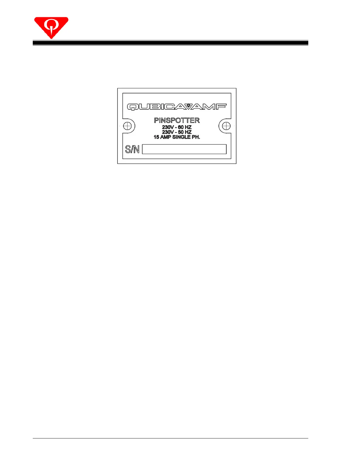
3.3 Electrical Drawings and Pinspotter Ratings
Figure 3-17
Shown above are the pinspotter’s voltage, frequency, and current ratings. Also,
each machine is serialized with a date-of-manufacture- based serial number.
For information pertaining to the QubicaAMF XLi EDGE Pinspotter’s electrical
connections, refer to Attachment A, QubicaAMF XLi EDGE Pinspotter Wiring
Diagram, 088-200-678.
3.4 Pin Distributor
For information pertaining to the XLi EDGE Pin Distributor, refer to Attachment B,
XLi EDGEPinDistributor Manual, P/N 400-088-121.
3.5 Positive Ball Lift (PBL)
For information pertaining to the Positive Ball Lift, refer to Attachment C,
QubicaAMF Pinspotter Positive Ball Lift Manual, 400-088-011-01.
3.6 Chassis
For information pertaining to the operation of the pinspotter chassis, refer to
Attachment D, XLi QubicaAMF Pinspotter Chassis Manual, P/N 400-088-009.
3.7 Motors & Gearboxes
 Loading...