XLi EDGE Pinspotter
Section 4-2 4.2-14 Rev. Date: 10/2016
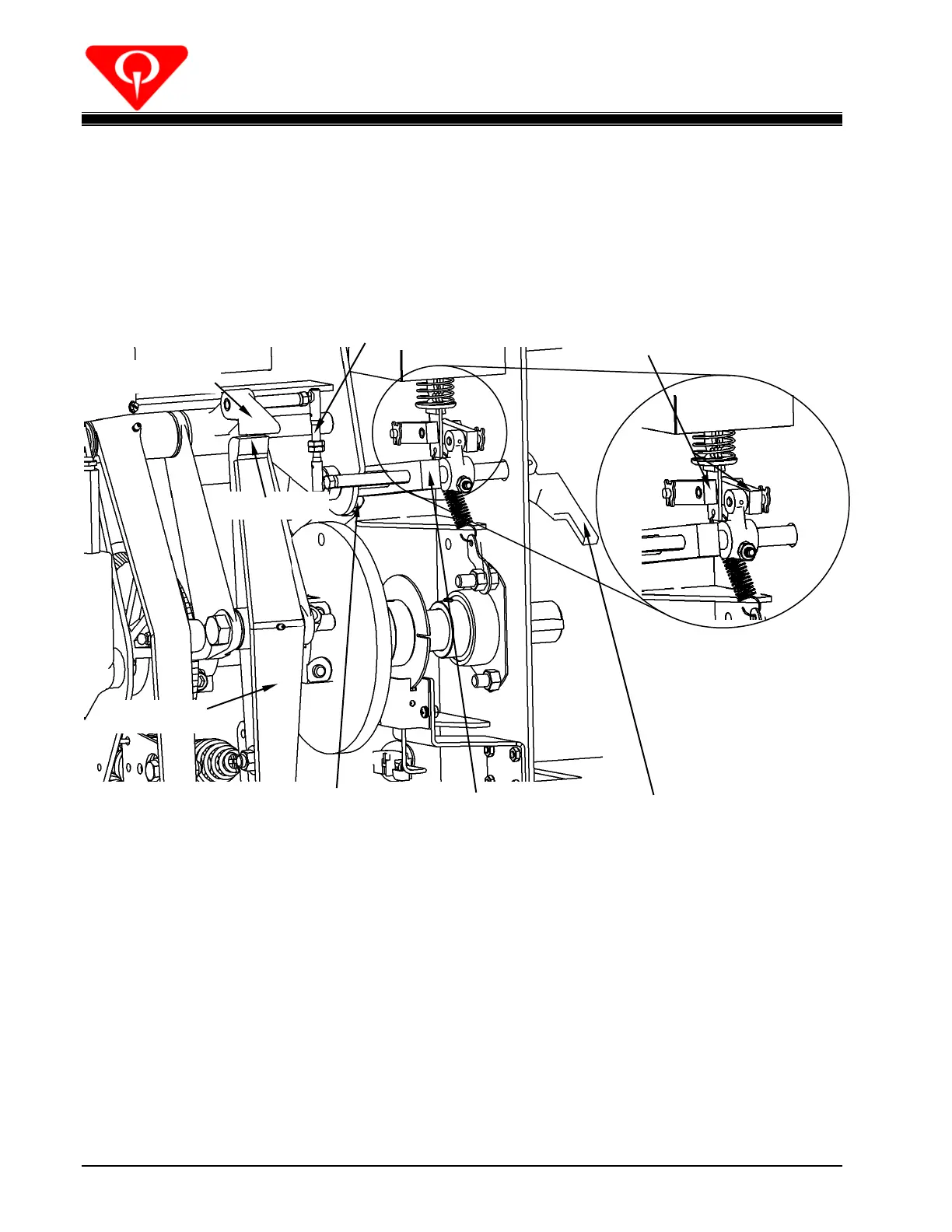
4.2.2.14 Spotting Linkage Adjustments
1. With the table at the home position, the distance between the end of the shuttle stop lever
assembly and the adjusting bolt (see Figure 4.2-15) should be .015 inches. Adjust the bolt to
provide this spacing and then tighten the jam nut.
Figure 4.2-15
2. When the spotting solenoid is actuated, the cam lever should be locked in the down position.
This locked condition is established when solenoid engagement causes the two rectangular
links (see Figure 4.2-15) to align horizontally. Test for locking by manually engaging the
solenoid and then pulling up on the cam lever. The lever must remain in the down position.
This rigidity is necessary to disengage the eccentric’s latching mechanism during a spotting
cycle. If the lever moves, some part of the linkage is worn or broken and must be replaced.
3. With the table at the home position, insert the thicker end of gauge (088-001-217) between
the top of the spot lever and the bottom edge of the spot latch. Adjust the vertical linkage to
obtain a .188-inch clearance and then tighten the jam nuts against each other.
Shuttle Stop
Lever Assembly
 Loading...