Section 4.2
Machine Adjustments
400-088-120-02 4.2-3 Rev Date: 10/2016
4.2.2 Table Adjustments
4.2.2.1 Tie Rod Adjustment
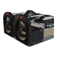
Throughout this section, references to adjusting the various tie rods are
made. A tie rod (Figure 4.2-3) is a device that consists of two threaded
sections and a center section into which the threaded sections fit. On
most tie rods, one threaded section has standard right-hand threads, and
the other threaded section has left-hand threads. Turning the center
section increases or decreases the tie rod’s overall length. The end with
the left-hand threads can be identified by a line scribed around the
circumference of the center section near the end. It is helpful to know
which end is left threaded because there is a jam nut on each of the
threaded sections, and the left-threaded nut must be turned opposite the
normal direction to loosen. A few tie rods have right-hand threads on
both ends to prevent the tie rod from going out of adjustment during
operation, and at least one end must be disconnected for it to be
adjusted. Loosen the jam nuts before making any tie rod adjustments,
and tighten them after adjustments have been made.
The following Table adjustments are presented in the order in which they
should be performed for optimal results.
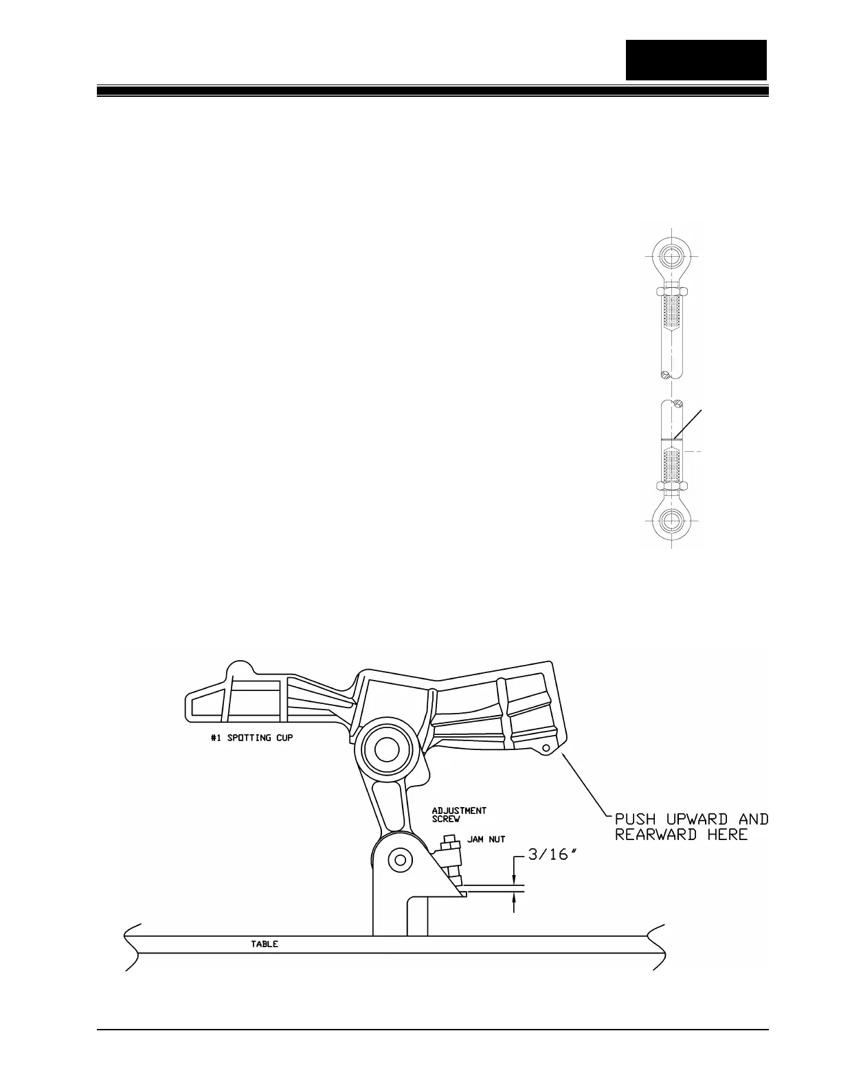
4.2.2.2 Table Leg Screw Adjustment
Figure 4.2-4
Line indicates
end of tie rod
with left-hand
threads.
 Loading...