Section 3.
Pinspotter Mechanical Operation
400-088-120-02 Page 3-7 Rev. Date: 10/2016
3.2 Pinspotter Electrical Operation
Power to the pinspotter is supplied via the chassis. The chassis has three power
supplies: one for each pinspotter’s electrical components (the cables with the large
blue connectors), and a logic power supply that provides control power for the
various machine functions.
Before turning on control power to the pinspotter chassis, ensure that the red E-
stop buttons on the chassis and at the front of the pinspotters are not depressed.
These buttons have a lock-in feature that requires that they be pulled out to its
normal position. If an E-stop button is in the depressed position when chassis
logic power is energized, the pinspotters will not turn on and the E-STOP ERROR
message will not be displayed. If an E-Stop button is pressed after logic power is
turned on, the chassis will sense this and display the E-STOP ERROR message.
3.2.1. Motors
The machine employs three capacitor-start induction motors. All three motors are
fractional horsepower units. These motors are designed to operate in a voltage
range of 208VAC to 240VAC and are available in 50 Hz or 60 Hz, to match the
electrical power in your area. All motors have gear reducer units attached.
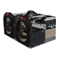
Two of the three motors (Figure 3-10) are mounted on
the front end and operate the table and sweep. These
motors operate intermittently as required and are
equipped with a brake and an encoder assembly that
is used to provide position indication for the table and
sweep. The Table and Sweep motors are
interchangeable.
The third motor is mounted on the back end and
supplies power to drive the pin elevator, the pin
conveyer, the ball lift (PBL), and the distributor. This
motor runs continuously.
 Loading...