Section 4.2
Machine Adjustments
400-088-120-02 4.2-7 Rev. Date: 10/2016
2. Remove the Spot Rod from the Spot Lever.
3. Remove the two Tension Springs from the 7-10 Yoke Shaft to the Table Uprights.
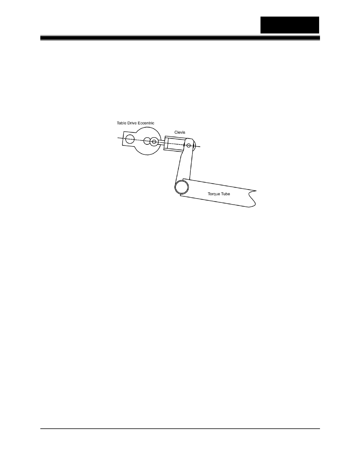
4. Crank the Table to Bottom Dead Center (its lowest point). Table Drive Shaft, Eccentric stud,
and Clevis bolt through Torque Tube all in line as seen in Figure 4.2-9).
Figure 4.2-9
5. Loosen the 6 nuts on the carriage bolts that hold the Table to the Table Uprights. The Table
Uprights should be perpendicular to the pin deck.
6. Move the Table so that the points of the Flags are exactly over the center spots of the 1, 7, and
10-pin spots.
7. Tighten all six carriage bolt nuts.
8. Plug the Table Motor back in.
9. Run the Table to the home position.
10. Reconnect the Table Spot Rod.
4.2.2.5 Spot Rod Adjustment
1. With the Bin full of pins, hold down on the Cam Lever to manually actuate the Spot Linkage.
2. Run the Table down to just before the point where the pins touch the pin deck.
3. Unplug the Table and Sweep Motors.
 Loading...