XLi EDGE Pinspotter
Section 4-2 4.2-34 Rev. Date: 10/2016
2. Disconnect the pin conveyor drive belt from the drive pulley on the rear roller, and remove the
pulley from the roller.
3. Remove the paddle from the rudder arm.
4. Release the front roller from its bearing supports as follows:
a. Insert the belt installation tool between the front roller and the tail plank.
b. Apply pressure toward the rear of the machine. When the bearing support bracket clears the
hole in the kickback plate, insert a retaining pin (792-501-001) into the hole.
c. Repeat steps 3a and 3b for the other side of the machine.
4. Remove the front roller by rolling it over the bounce plate and out the ball exit opening into
the adjacent machine.
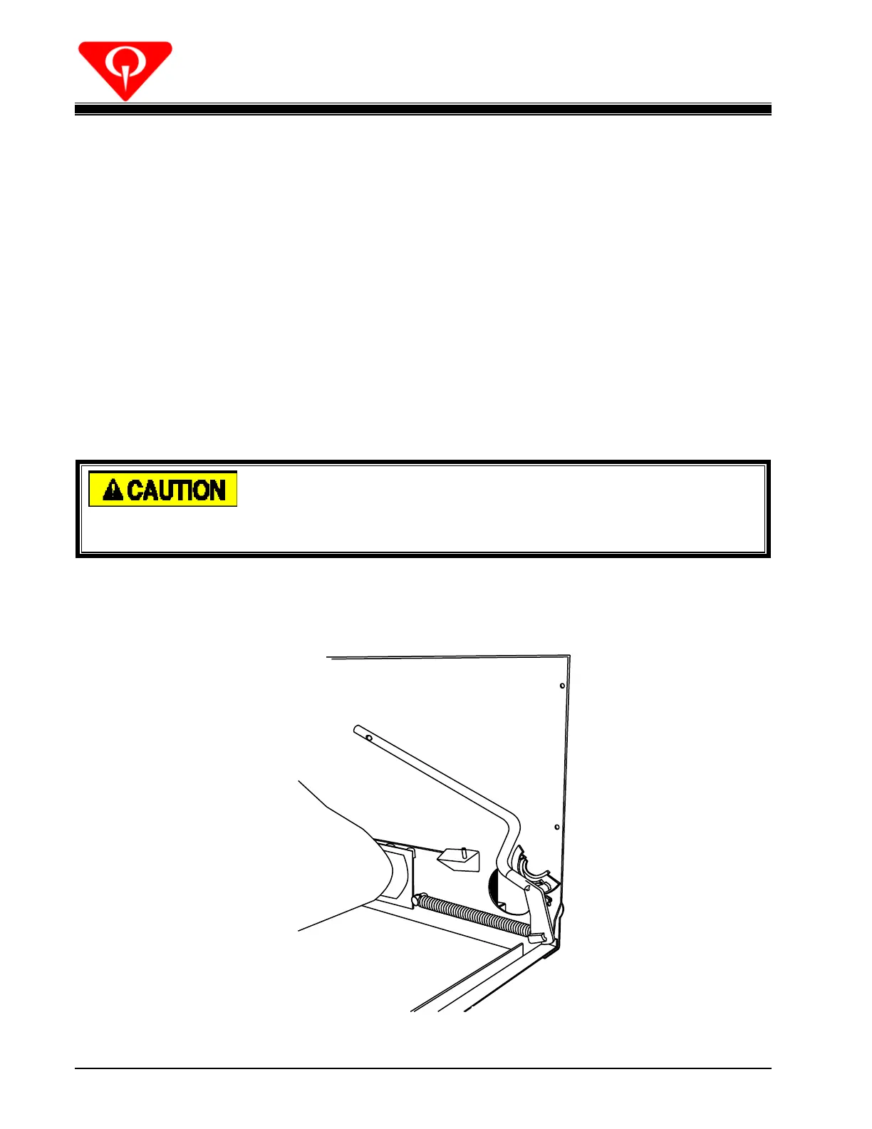
Spring tension on the roller bearing support brackets should be
removed while working in the pit. Personnel can be injured if a
retaining pin is accidentally knocked out.
5. Make the machine safe for entry as follows:
a. Place the belt installation tool flag (792-502-002) onto the bearing support assembly (see
Figure 4.2-36).
Figure 4.2-36
 Loading...