Remote Control - Commands
R&S
®
NRP2
198User Manual 1173.9157.02 ─ 03
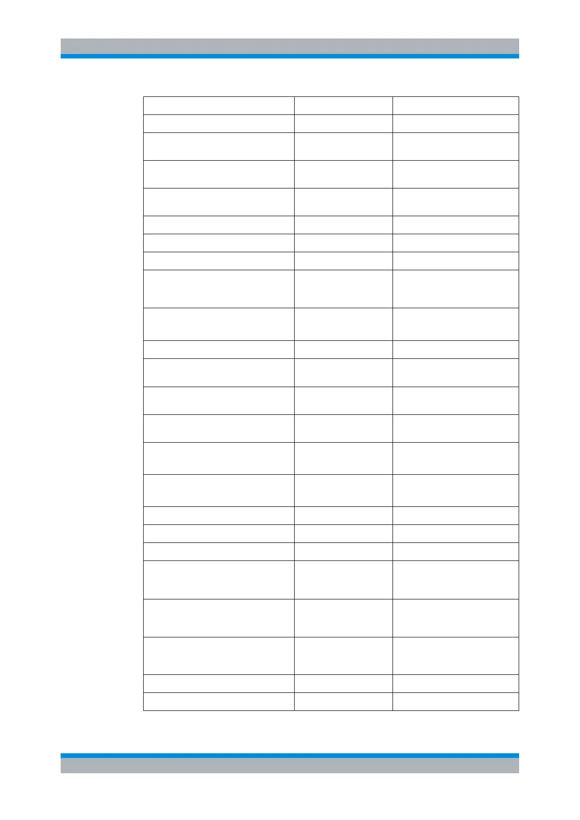
Command Preset and *RST value Remark
DISP:SIZE NORM
Automatic window sizes.
DISP<[1]..4> ON | OFF
A window will automatically be
opened for each sensor.
DISP<[1]..4>:TRAC:LOW -120 DBM
Lower limit of power axis in Trace
mode
DISP<[1]..4>:TRAC:UPP 30 DBM
Upper limit of power axis in Trace
mode
DISP<[1]..4>:TSL 1
First timeslot
DISP<[1]..4>:UPD NORM
Frequent display updates.
FORM ASC
Measured data in ASCII format.
FORM:BORD NORM
"Big-Endian" byte sequence of
measured data, if FORMat REAL is
selected.
INIT[1..4|:ALL]:CONT ON
OFF
PRES and SYSTem:PRESet.
*RST
INIT[1..4|:ALL]:DIS OFF
MEM:… -
The settings in the MEMory com-
mand system will not be affected.
OUTP:REC1:FEED "CALC1"
Analog outputs are fed by the first
calculate block.
OUTP:REC2:FEED "CALC2"
Analog outputs are fed by the sec-
ond calculate block.
OUTP:REC[1..2]:LIM:LOW
-20 DBM or
0 DB
0 V equivalent at analog output.
OUTP:REC[1..2]:LIM:UPP
20 DBM or
10 DB
3 V equivalent at analog output.
OUTP:REC1:STAT ON
Analog output active.
OUTP:REC2:STAT OFF
Trigger input active.
OUTP:ROSC OFF
Test generator is switched off.
OUTP:TTL:ACT LOW
OUTPut:TTL:LVOLtage is
applied to the TTL output if a limit is
violated.
OUTP:TTL:FAIL HIGH
OUTPut:TTL:HVOLtage is
applied to the TTL output if a limit is
violated.
OUTP:TTL:FEED "CALC1:LIM"
The TTL output is fed by the limit
monitoring function of calculate
block 1.
OUTP:TTL:HVOLT 3.3 V
High voltage at TTL output
OUTP:TTL:LVOLT 0.0 V
Low voltage at TTL output
Common Commands to IEEE 488.2