10
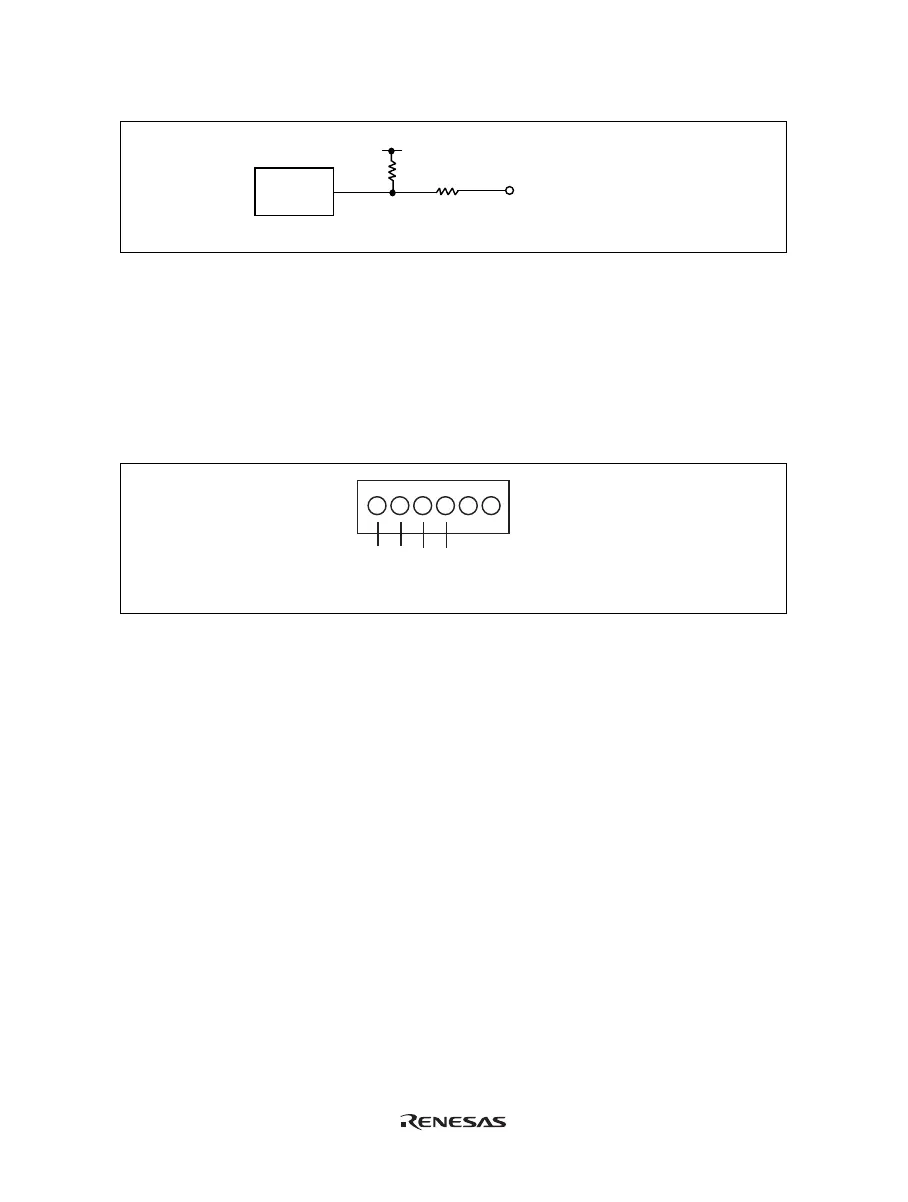
The interface circuit for the external probe 1 is shown in figure 2.8.
10 k
External probe 1, 2, 3, 4
HD151015
22
Vcc
Ω
Ω
Figure 2.8 Interface Circuit for External Probe 1
The trigger output is controlled by event channel 8 and is an active low signal. The trigger output is available as
either T5V (within the range from 2.5 V to 5 V; does not depend on the user V
CC
level) or TUV
CC
(the user V
CC
level).
2.6.5 External Probe 2 (EXT2)/Trigger Output
A 6-pin connector, marked EXT2 (on the left under the user system interface cable connector), on the emulator
case accommodates four trigger outputs. The pin assignment of this connector is shown in figure 2.9.
EXT2
Trigger output
1234
56
Figure 2.9 External Probe 2 Connector
The trigger output is an active high signal which is output during the read or write cycles when a trace condition
(1 to 4) of the bus monitor function is satisfied. The trigger output is available as user V
CC
level. Note that,
however, some products do not support the external probe 2 (EXT2).

 Loading...


