16. MULTI-MASTER I
2
C bus INTERFACE
puorG92/C61M
page 262
854fo7002,03.raM21.1.veR
2110-1010B90JER
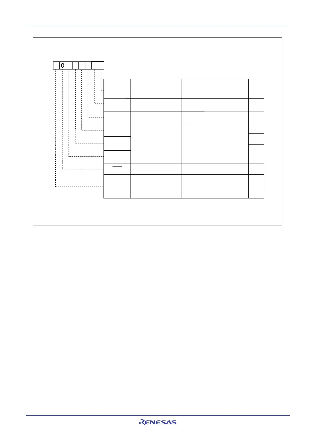
Figure 16.7 S4D0 Register
SCPIN
Reserved bit
ICK4
ICK3
ICK2
TOSEL
TOF
TOE
FunctionBit NameBit Symbol
00
16
After Reset
02E7
16
AddressSymbol
S4D0
0
ontrol Re
ister 2
2
RW
7
4
2b1b0
0: Long time
1: Short time
STOP condition detection
interrupt request bit
Set to 0
b5 b4 b3
0 0 0 V
IIC
set by ICK1 and ICK0
bits in S3D0 register
0 0 1 V
IIC
= 1/2.5 f
IIC
0 1 0 V
IIC
= 1/3 f
IIC
0 1 1 V
IIC
= 1/5 f
IIC
1 0 0 V
IIC
= 1/6 f
IIC
Do not set other than the above values
Time out detection time
select bit
Time out detection flag
Time out detection
function enable bit
I
2
C bus system clock
select bits
0: No I
2
C bus interface interrupt
request
1: I
2
C bus interface interrupt
request
0: Not detected
1: Detected
0: Disabled
1: Enabled
RW
RO
RW
RW
RW
RW
RW
RW
(b6)
(1)
NOTE:
1. When the PCLK0 bit in the PCLKR register is set to 0, f
IIC = f2. When the PCLK0 bit is set to 1, fIIC=f1.
 Loading...


