M126/M127/M128 6-64 SM
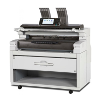
6.5.11 OPERATOR PANEL SERVICE CHECK
Inspect the operator panel cable for damage. Make sure the cable is plugged in securely. Run
POST, and check each light for proper operation ( p.6-2 "Power–On Self Test (POST)
Sequence").
Touch screen operator panel service check
FRU Action
Operator panel
Display
Operator panel
keyboard
Controller board
WARNING:
Do not replace the
engine board and
controller board at
the same time. Each
board contains the
machine settings.
When either of these
boards is new, it
obtains the settings
from the other
board. Settings are
lost when both are
new and replaced at
the same time.
Touchscreen display
If the touchscreen display does not come on or indicator LED on
the keyboard doesn’t illuminate, then open the controller board
cage and locate the operator panel connector at J34. Make sure
the cable is properly connected to the controller board and the
controller board has input voltage to it.
With the machine on, verify the following on connector J34:
Pins 1, 3, 5, and 6: 3.3 v
Pin 10, 16, 17, and 18: 5 v
Pins 2, 9, and 15: GND
If any are incorrect, then see “Controller Board Service Check” in
“Troubleshooting”.
If these are approximately correct and the operator panel is not
functioning:
1. Turn the machine off.
2. Remove the left and right covers.
3. Tilt the operator panel keyboard and verify the UICC cable is
properly connected to the keyboard at connector J10.
4. If the cable is properly connected at both ends, check the
cable for continuity. If the cable fails, replace the UICC cable.
5. Reconnect the UICC cable, and verify the display ribbon
cables are properly connected to J3 and J12 on the keyboard.
6. Restart the machine. If the eight LEDs on the bottom of the
keyboard card illuminate, but the display fails to illuminate,
replace the touchscreen display.
7. If the eight LEDs fail to illuminate, replace the keyboard.
 Loading...