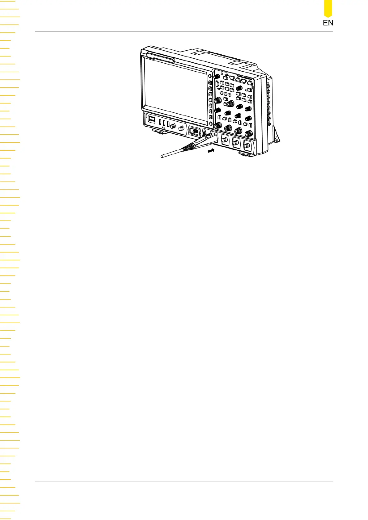
Figure 4.8 Connect the Active Probe
4. Use the probe's auxiliary device to connect the probe head to the circuit under
test. For details about the probes, refer to
RP7000 Series Active Probe User Guide
.
After you connect the active probe, you can make probe calibration and offset
voltage adjustment.
Connect the logic probe
1. Connect the output terminal of the logic probe to the digital channel input
terminal on the front panel of the oscilloscope in the correct direction, as shown in
Figure 4.9
.
2. Connect the other terminal of the logic probe to the signal terminal under test.
RIGOL's MSO8000 series has a standard configuration of a logic probe RPL2316. To
apply to different application scenarios, RPL2316 provides three connection
methods to connect the signal under test. For details, refer to
RPL2316 Logic Probe
User Guide
.
Quick Start
18
Copyright ©RIGOL TECHNOLOGIES CO., LTD. All rights reserved.