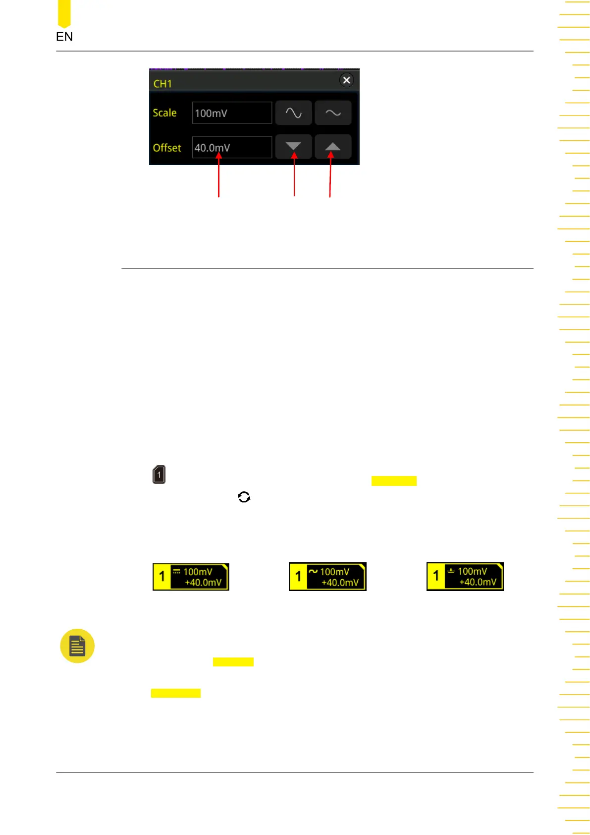
Value Input Field
Decrease
Increase
5.5 Channel Coupling
The undesired signals can be filtered out by setting the coupling mode. For example,
the signal under test is a square waveform with DC offset.
• When the coupling mode is "DC": the DC and AC components of the signal
under test can both pass the channel.
• When the coupling mode is "AC": the DC components of the signal under test
are blocked.
• When the coupling mode is "GND": the DC and AC components of the signal
under test are both blocked.
Press to open the CH1 setting menu.Then, press Coupling continuously or rotate
the multifunction knob to select the desired coupling mode (by default, it is DC).
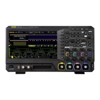
The current coupling mode is displayed in the channel status label at the bottom of
the screen, as shown in the figure below. You can also enable the touch screen, and
then touch the CH1 setting menu to select the desired coupling mode.
DC
AC GND
NOTE
• When the input impedance is set to "50 Ω", the channel coupling is set to DC coupling by
force, and the Coupling menu is grayed out and cannot be modified.
• When the coupling mode is "AC", the input impedance is set to 1 MΩ by force, and the
Impedance menu is grayed out and cannot be modified.
To Set the Vertical System
Copyright ©RIGOL TECHNOLOGIES CO., LTD. All rights reserved.
51