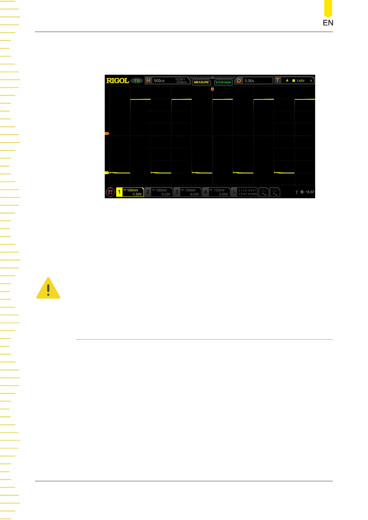
5. Observe the waveform on the display. In normal condition, the square waveform as
shown in
Figure 4.11
should be displayed.
Figure 4.11 Square Waveform Signal
6. Use the same method to test the other channels. If the square waveforms actually
shown do not match that in the figure above, please perform "
Probe
Compensation
" introduced in the next section.
WARNING
To avoid electric shock when using the probe, please make sure that the insulated wire of
the probe is in good condition. Do not touch the metallic part of the probe when the
probe is connected to high voltage source.
4.3.7 Probe Compensation
When the probes are used for the first time, you should compensate the probes to
make them match the input channels of the oscilloscope. Non-compensated or
poorly compensated probes may cause measurement inaccuracy or errors. The probe
compensation procedures are as follows:
1. Perform Step 1, 2, 3 and 4 specified in "
Function Inspection
".
2. Check the displayed waveforms and compare them with the waveforms shown in
Figure 4.12
.
Quick Start
20
Copyright ©RIGOL TECHNOLOGIES CO., LTD. All rights reserved.