Rockwell Automation Publication 5094-UM001C-EN-P - April 2019 107
Chapter 7
Configure and Replace Safety Modules
This chapter describes how to configure your FLEX 5000™ safety I/O modules in
a Logix Designer application project.
This chapter does not explain the user-configurable parameters, or corresponding
module features, in your Logix Designer application project.
For detailed information about module features, see the following:
• Chapter 2
, Common Digital I/O Module Features on page 45
• Chapter 3, Input Module Features on page 53
• Chapter 4, Output Module Features on page 57
• Chapter 5, Safety I/O Module Features on page 71
Topic Page
Before You Begin 108
Create a New Module 108
Edit the Module Configuration Common Categories 110
Edit the 5094-IB16S or 5094-IB16SXT Module Configuration Categories 115
Edit the 5094-OB16S or 5094-OB16SXT Module Configuration Category 117
View the Module Tags 117
Replace a Module 118
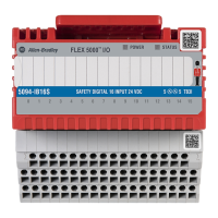
STATUS
POWER
SAFETY DIGITAL 16 INPUT 24 VDC
5094-IB16S
5
5
TB3I
FLEX 5000
TM
I/O
0 1 2 3 4 5 6 7 8 9 10 11 12 13 14 15
IMPORTANT You must use the Logix Designer application, version 32 or greater with the
modules.
IMPORTANT By default, all safety input and output channels on FLEX 5000 safety I/O
modules are disabled.
You must configure each point that is used in a safety application.
 Loading...
