Rockwell Automation Publication 5094-UM001C-EN-P - April 2019 81
Safety I/O Module Features Chapter 5
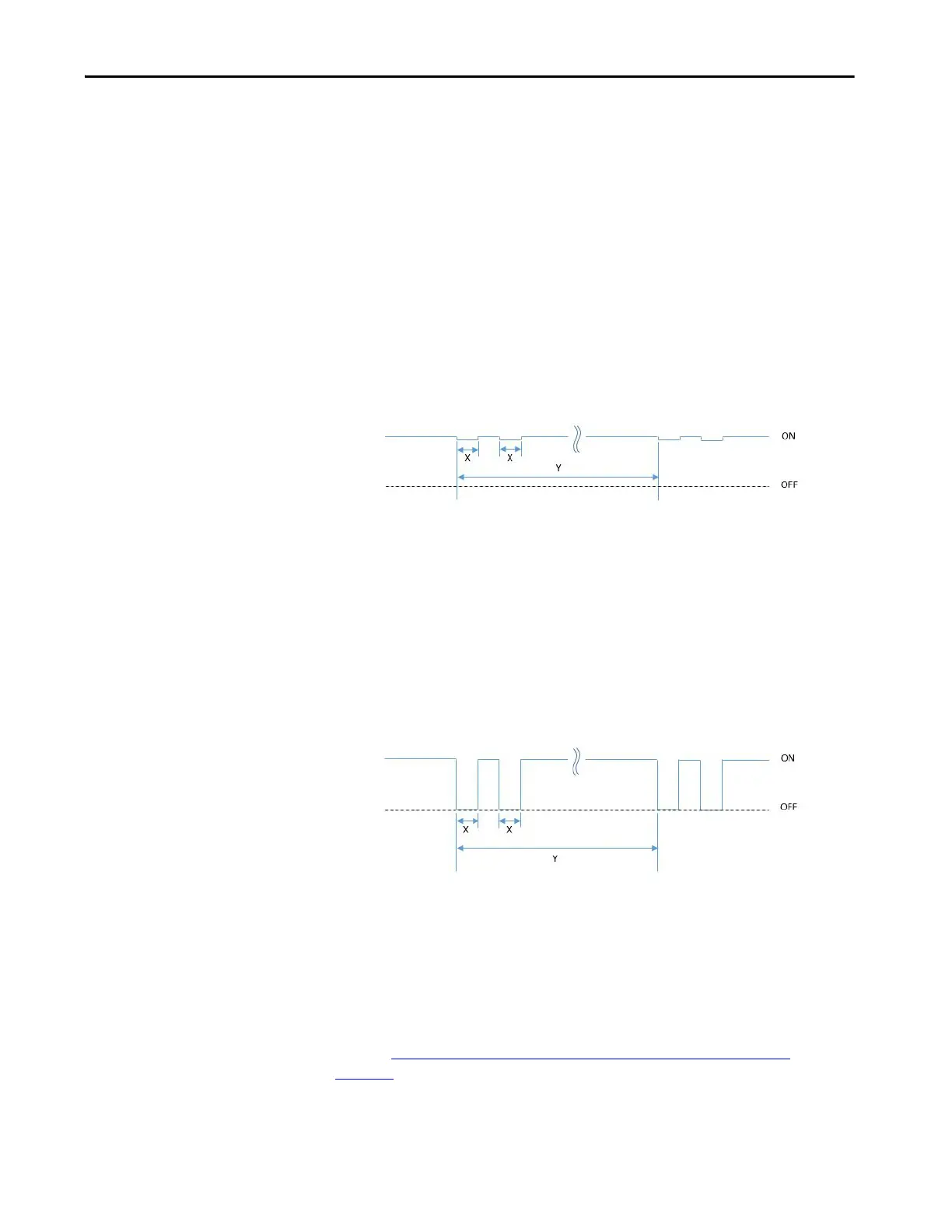
Safety and Safety Pulse Test Mode
The Safety Output can be configured to two types of point modes:
•Safety Mode
• Safety Pulse Test Mode
When the safety output is configured to Safety Mode, the safety output channel
continuously test the ability of the safety output switching elements ability to
turn off while maintaining the safety output at its nominal voltage with less than
1 Volt change. This small voltage variation during the pulse test is insignificant
for most of the connected device.
If an error is detected, the safety output data and individual safety output status
turn off.
On the 5094-OB16S and 5094-OB16SXT modules, the pulse width (X) is less
than 500 µs, and the pulse period (Y) is less than 200 ms.
When the safety output is configured to Safety Pulse Test Mode, the safety
output channel continuously test the ability of the safety output to remove power
from the output terminals of the module. The safety output turn off momentarily
during the pulse test duration.
If an error is detected, the safety output data and individual safety output status
turn off.
On the 5094-OB16S and 5094-OB16SXT modules, the pulse width (X) is less
than 500 µs, and the pulse period (Y) is less than 200 ms.
Refer to 5094-OB16S and 5094-OB16SXT Module Wiring Diagrams
on
page 161
for more details about applying Safety Mode and Safety Pulse Test
Mode in your application.
TIP To help prevent the test pulse from causing the connected device to
malfunction, pay careful attention to the input response time of the output
device.

 Loading...


