126 Rockwell Automation Publication 5094-UM001C-EN-P - April 2019
Appendix A Troubleshoot Your Module
FLEX 5000 Digital Input
Modules Status Indicators
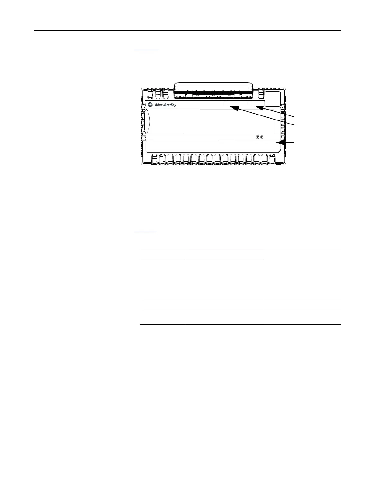
Figure 16 shows the status indicators on FLEX 5000 input modules.
Figure 16 - FLEX 5000 Input Module Status Indicators
Tabl e 22 describes the I/O Status indicators on FLEX 5000 input modules.
STATUS
POWER
DIGITAL 16 INPUT 24 VDC
5094-IB16
1
1
TB3
FLEX 5000
TM
I/O
0 1 2 3 4 5 6 7 8 9 10 11 12 13 14 15
Input Point 0 (I00)
Input Point 1 (I01)
Input Point 2 (I02)
Input Point 3 (I03)
Input Point 4 (I04)
Input Point 5 (I05)
Input Point 6 (I06)
Input Point 7 (I07)
Input Point 8 (I08)
Input Point 9 (I09)
Input Point 10 (I10)
Input Point 11 (I11)
Input Point 12 (I12)
Input Point 13 (I13)
Input Point 14 (I14)
Input Point 15 (I15)
SA power status indicator
I/O status indicators
5094-IB16, 5094-IB16XT
Module status indicator
Table 22 - I/O Status Indicators - FLEX 5000 Input Modules
Indicator State Description Recommended Action
Off One of the following:
• The input point is Off.
• There is no backplane power.
One of the following:
• Confirm that the input point is
configured properly.
• Confirm that there is backplane power
supplied through the FLEX 5000
EtherNet/IP adapter.
Steady yellow The input point is operating normally. None
Flashing red A Field Power Loss condition exists. Locate and correct the cause of field power
loss condition.

 Loading...


