Rockwell Automation Publication 5094-UM001C-EN-P - April 2019 125
Troubleshoot Your Module Appendix A
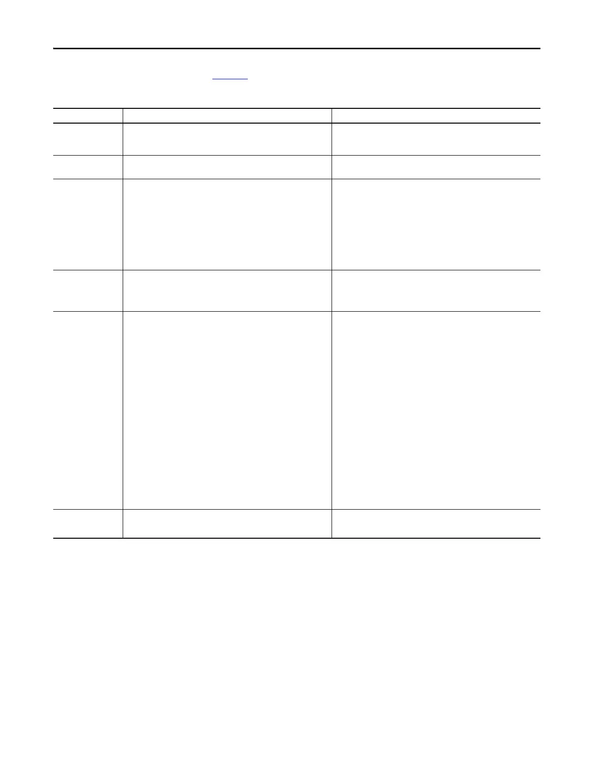
Module Status Indicator
Tabl e 21 describes the Module Status indicator on FLEX 5000 I/O modules.
Table 21 - Module Status Indicator - FLEX 5000 Digital I/O Modules
Indicator State Description Recommended Action
Off The module is not powered. Complete the following actions:
1. Confirm that the system is powered.
2. Confirm that the module is installed properly.
Steady green The module has a connection to the owner-controller and is operating
normally.
None
Flashing green One of the following conditions exist:
• The module has powered up successfully.
• The module is OK, but it does not have a connection.
No connection can result from missing, incomplete, or incorrect
module configuration.
For safety modules only - A connection can be established with the
controller, but initial time coordination exchange is not complete.
Connection to an output module is in the idle state.
Complete the following actions:
• Troubleshoot your Logix Designer application to determine what is
preventing a connection from the module to the controller and correct
the issue.
• Confirm that the system conditions require the controller to be in
Remote Run mode or Run mode, transition the controller to one of those
modes.
Steady red The module experienced a nonrecoverable fault. Complete the following actions:
1. Cycle power to the module.
2. If the status indicator remains in the steady red state, replace the
module.
Flashing red One of the following conditions exist:
• A module firmware update is in progress.
• A module firmware update attempt failed.
• The device has experienced a recoverable fault.
• A connection to the module has timed out.
Complete one of the following:
• Let the firmware update progress complete.
• Reattempt a firmware update after one fails.
• Use the Logix Designer application to determine the cause of the
module fault.
The Connection and Module Info categories of the modules
configuration indicate the fault type.
To clear a recoverable fault, complete one of the following:
– Cycle module power.
– Click Reset Module in the Logix Designer project via the Module Info
category of the Module Properties dialog box.
If the fault does not clear after cycling power and clicking Reset Module,
contact Rockwell Automation Technical Support.
• Use the Logix Designer application to determine if a connection has
timed out. The Connection category in the Module Properties for the
module indicates the module state, including if a connection has
timed out.
If a connection has timed out, determine the cause and correct it. For
example, a cable failure can cause a connection timeout.
Red/green (railroad)
For safety modules only - This pattern indicates that a UNID for the
safety device needs to be configured.
None

 Loading...


