Rockwell Automation Publication 5094-UM001C-EN-P - April 2019 131
Troubleshoot Your Module Appendix A
Use the Logix Designer
Application for
Troubleshooting
In addition to the status indicator display on the module, the Logix Designer
application indicates the presence of fault conditions.
Fault conditions are reported in the following ways:
• Warning Signal in the I/O Configuration Tree
• Status and Fault Information in Module Properties Categories
• Logix Designer Application Tag Editor
Warning Signal in the I/O Configuration Tree
As shown in Figure 21, a warning icon appears in the I/O Configuration tree
when a fault occurs.
Figure 21 - Warning Icon in Controller Organizer
STATUS
POWER
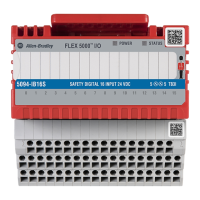
SAFETY DIGITAL 16 INPUT 24 VDC
5094-IB16S
5
5
TB3I
FLEX 5000
TM
I/O
0 1 2 3 4 5 6 7 8 9 10 11 12 13 14 15
STATUS
POWER
DIGITAL 16 INPUT 24 VDC
5094-IB16
1
1
TB3
FLEX 5000
TM
I/O
0 1 2 3 4 5 6 7 8 9 10 11 12 13 14 15
Safety Modules
Standard Modules
 Loading...
