20 Rockwell Automation Publication 5094-UM001C-EN-P - April 2019
Chapter 1 Digital I/O Module Operation in a Logix 5000 Control System
Module Overview
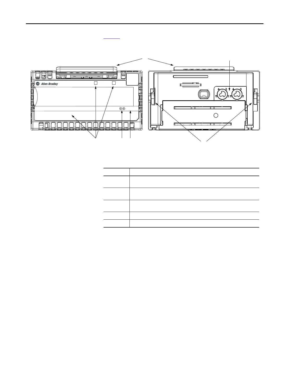
Figure 3 shows the parts of an example FLEX 5000 standard I/O module.
Figure 3 - Example FLEX 5000 Standard I/O Module
STATUS
POWER
DIGITAL 16 INPUT 24 VDC
5094-IB16
1
1
TB3
FLEX 5000
TM
I/O
0 1 2 3 4 5 6 7 8 9 10 11 12 13 14 15
Table 4 - FLEX 5000 Standard I/O Module Parts
Item Description
1 Status indicators - Displays the status of communication, module health, and input/output
devices. Indicators help with troubleshooting anomalies
2 Release lever - Disengages the latching hooks to allow removal of the module from the
terminal base assembly
3 Module keying - Indicates the keying position the terminal base assembly must be configured
to before installing the module
4 Terminal base - Indicates the type of terminal base assembly to use with the module
5 Latching hooks - Securely installs FLEX 5000 modules on the terminal base assembly

 Loading...


