156 Rockwell Automation Publication 5094-UM001C-EN-P - April 2019
Appendix C Application/Wiring Examples for Safety I/O Modules
5094-IB16S and
5094-IB16SXT Module
Wiring Diagrams
The following wiring diagrams show the input modules in Safety Mode and
Safety Pulse Mode.
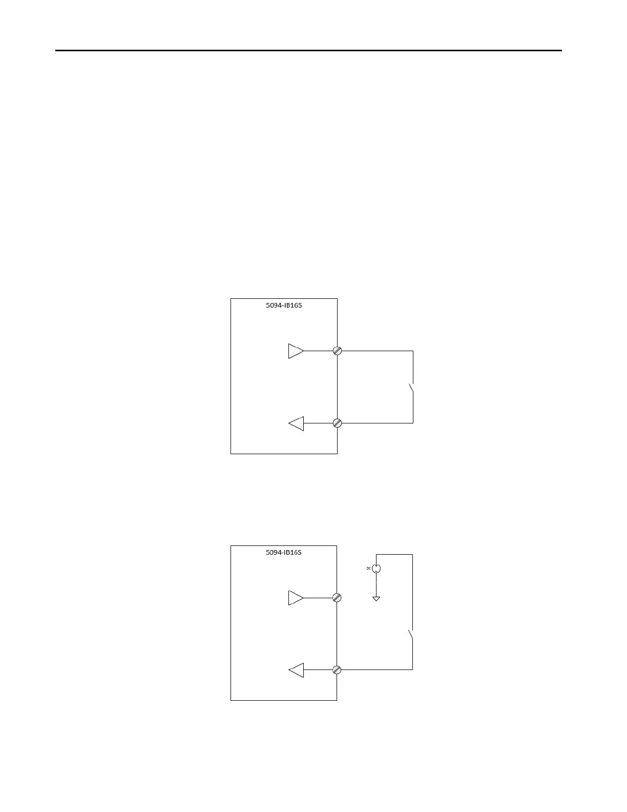
Figure 28 - 5094-IB16S Module - SIL 3, PLc, Cat. 2 in Safety Pulse Mode or Safety Mode
Figure 29 - 5094-IB16S Module - SIL 3, PLc, Cat. 2 in Safety Mode
Test Output Association with Safety Input:
TO_0: SI_0, SI_8
TO_1: SI_1, SI_9
TO_2: SI_2, SI_10
TO_3: SI_3, SI_11
TO_4: SI_4, SI_12
TO_5: SI_5, SI_13
TO_6: SI_6, SI_14
TO_7: SI_7, SI_15
Note: In Safety Pulse mode, if external wiring short of 2 Safety inputs from the same Test Output point, the short
circuit is not detectable. Hence, in Dual Channel mode, use 2 Safety Inputs from different Test Output points.
SIL level and Category: SIL 3, PLc, Cat. 2
Fault Exclusion: None
Other: External connected device must be SIL 3 rated.
Point Mode: Safety Pulse Mode, Safety Mode
SI_n(n = 0...15)
TO_n(n = 0...7)
TO_n configured to Test Output with Pulse when using Safety
Pulse mode
TO_n configured to Power Supply when using Safety mode
TO_n
SI_n or SI_n+8
SIL level and Category: SIL 3, PLc, Cat. 2
Fault Exclusion: None
Other: External connected device must be
SIL 3 rated.
Point Mode: Safety Mode
SI_n(n = 0...15)
TO_n(n = 0...7)
TO_n
SI_n

 Loading...


