Rockwell Automation Publication 5094-UM001C-EN-P - April 2019 155
Appendix C
Application/Wiring Examples
for Safety I/O Modules
This appendix provides example wiring diagrams for the FLEX 5000™ I/O safety
modules that can be used in functional safety applications.
The wiring configuration affects the safety application level to which a
FLEX 5000 I/O safety module is suitable.
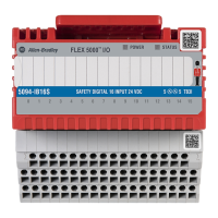
STATUS
POWER
SAFETY DIGITAL 16 INPUT 24 VDC
5094-IB16S
5
5
TB3I
FLEX 5000
TM
I/O
0 1 2 3 4 5 6 7 8 9 10 11 12 13 14 15
Topic Page
5094-IB16S and 5094-IB16SXT Module Wiring Diagrams 156
5094-OB16S and 5094-OB16SXT Module Wiring Diagrams 161
IMPORTANT Conformity to requirements of the safety category and safety integrity level
must be determined for the entire system.
 Loading...
