Rockwell Automation Publication 5094-UM001C-EN-P - April 2019 73
Safety I/O Module Features Chapter 5
Use Test Output with a Safety Input
A test output can be used in combination with a safety input for short circuit and
cross-channel fault detection.
Configure the test output as a pulse test source and associate it to a specific safety
input. The associated safety input must use a Point Mode = Safety Pulse Test.
These mappings are the only allowed and default digital-input-to-test-output
association mappings for Safety Pulse Test configuration. Only a test output that
is configured as Pulse Test can be used as test source.
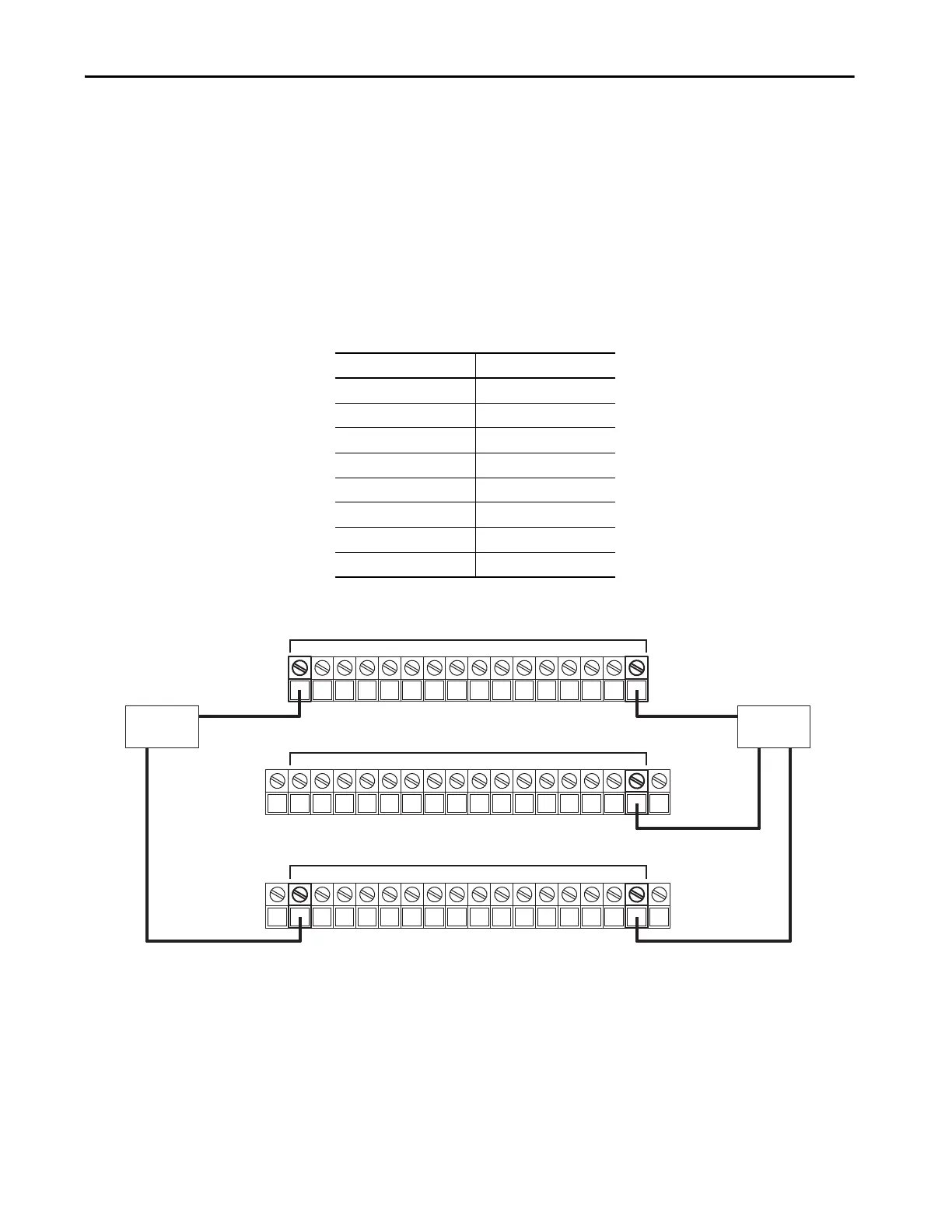
Figure 7 - FLEX 5000 I/O Safety Input Module - Input Connected to Test Output
This diagram shows:
• A 2-wire sensor is connected to safety input 0, with test output 0
configured as Test Pulse/Power Supply.
• A 3-wire sensor is connected to safety input 15, with test output 7
configured as Power Supply.
Safety Input Maps to Test Output
0,8 0
1,9 1
2,10 2
3,11 3
4,12 4
5,13 5
6,14 6
7,15 7
0 1 2 3 4 5 6 7 8 9 10 11 12 13 14 15
+ +–
SA– 16 17 18 19 20 21 22 23 24 25 26 27 28 29 30 31 SA–
Common
TO_0 TO_1 TO_2 TO_3 TO_4 TO_5 TO_6 TO_7 TO_0 TO_1 TO_2 TO_3 TO_4 TO_5 TO_6 TO_7
SA + 32 33 34 35 36 37 38 39 40 41 42 43 44 45 46 47 SA+
Test Outputs
Inputs

 Loading...


