Rockwell Automation Publication 5094-UM001C-EN-P - April 2019 161
Application/Wiring Examples for Safety I/O Modules Appendix C
5094-OB16S and
5094-OB16SXT Module
Wiring Diagrams
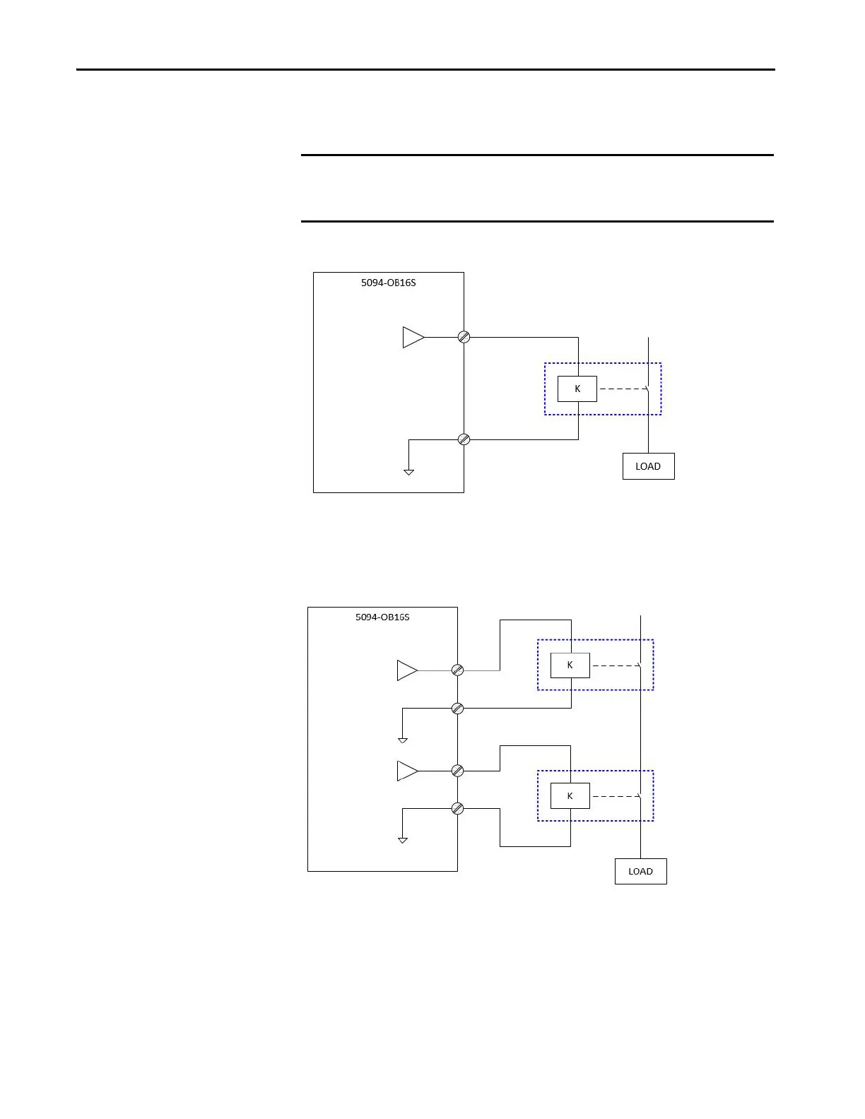
The following wiring diagrams show the output modules in Safety Mode and
Safety Pulse Mode.
Figure 38 - 5094-OB16S Module - SIL 3, PLc, Cat. 2 in Safety Mode or Safety Pulse Mode
Figure 39 - 5094-OB16S Module - SIL 3, PLe, Cat. 4 in Safety Pulse Mode
IMPORTANT The Safety level shown in the diagrams is applicable to the module itself.
Connected devices must have their own status monitoring to achieve
application safety level.
SIL level and Category: SIL 3, PLc, Cat. 2
Fault Exclusion: None
Other: External connected device must be SIL 3 rated.
Point Mode: Safety Pulse Mode, Safety Mode
n = 0…15
SO_n
SO_n_RETURN
n = 0…15
The channel pairs that support
Dual mode are:
Channel 0, 1 pair
Channel 2, 3 pair
Channel 4, 5 pair
Channel 6, 7 pair
Channel 8, 9 pair
Channel 10, 11 pair
Channel 12, 13 pair
Channel 14, 15 pair
SIL level and Category: SIL 3, PLe, Cat. 4
Fault Exclusion: None
Point Mode: Safety Pulse Mode
SO_n
SO_n_RETURN
SO_n+1
SO_n+1_RETURN

 Loading...


